


19
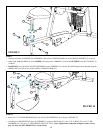
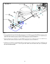
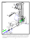
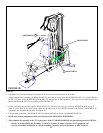
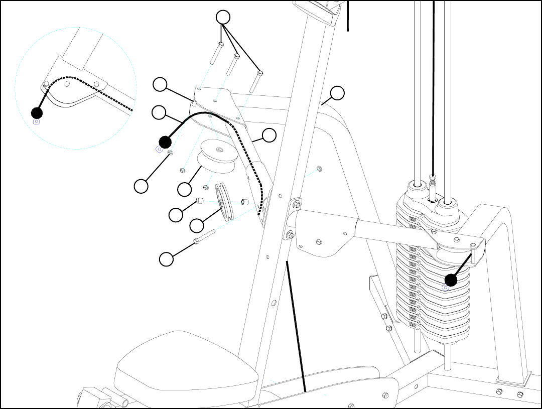
STEP 23:
FIGURE 23
38
39
6
31
63
3/8 X 2-3/4” 55
4
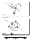
• Assemble one V-PULLEY (39) to the RIGHT ARM SUPPORT (4) using using one 3/8 X 2-3/4” BOLT (55) and one 3/8” LOCK
NUT (63). See FIGURE 23. (Note: Loop the ARM CABLE around the PULLEY prior to assembling the RIGHT ARM
SUPPORT.)
• Route the ARM CABLE (31) through the RIGHT ARM (6) as shown in FIGURE 23.
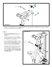
• Assemble one 4-1/2” PULLEY (38) to the RIGHT ARM (6) using one 3/8 X 2-3/4” BOLT (55), two 3/8 X 1/2” SPACERS (50) and
one 3/8” LOCK NUT (63). See FIGURE 23. (Note: Loop the ARM CABLE around the PULLEY prior to assembling the
RIGHT ARM.)
• SECURELY assemble one 2” NYLON SPACER (56) to the RIGHT ARM SUPPORT (4) using one 3/8 X 2-3/4” BOLT (55) and
one 3/8” LOCK NUT (63). See FIGURE 23.
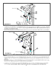
• Assemble the RIGHT ARM (6) to the RIGHT ARM SUPPORT (4) using one 3/8 X 2-3/4” BOLT (55) and one 3/8” LOCK NUT
(63). See FIGURE 20. (Note: Make sure the ARM CABLE runs in FRONT of the bolt as shown!.)
3/8 X 2-3/4” 55
50
56