


6
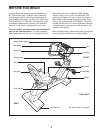
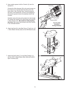
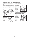
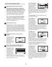
2. While another person lifts the rear of the Frame (1),
attach the Rear Stabilizer (16) to the Frame with four
M8 x 40mm Button Screws (54) and four M8 Split
Washers (55).
3
2
1
64
64
38
38
43
71
71
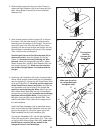
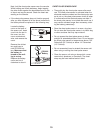
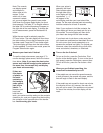
3. Have another person hold the Upright (2) in the posi-
tion shown. See the inset drawing. Locate the wire
extending from the bottom of the Upright.
Tie the wire
around the end of the W
ire Harness (43) as shown.
Carefully pull the wire up through the Upright until the
Wire Harness is extending from the top of the Upright.
Then, untie the wire and discard it.
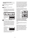
Carefully pull the end of the Wire Harness (43) to
remove any slack. Insert the Upright (2) into the
Frame (1); be careful to avoid pinching the Wire
Harness. Attach the Upright with two M10 x 118mm
Button Screws (64), two M10 Split Washers (38), and
two Upright Spacers (71). Make sure the concave
end of each Upright Spacer is turned toward the
Upright.
Do not pinch
the Wire
Harness (43)
during this
step.
16
1
55
55
54
54
2
43
Wire
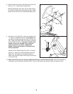
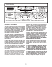
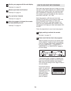
4. Identify the Left Handlebar (32), which is marked with a
sticker. While another person holds the Left Handlebar
near the Upright (2), connect the left Pulse Sensor Wire
(6) to the Pulse W
ire (3).
Carefully pull the upper end
of the Pulse Wire to remove any slack, and slide the
Left Handlebar onto the left tube on the Upright; be
careful to avoid pinching the W
ires.
Next, insert two
M8 x 40mm Button Bolts (68) into the Left Handlebar
and the tube on the Upright; be careful not to damage
the Wires with the Button Bolts. Finger tighten two
M8 Nylon Locknuts (69) onto the Button Bolts.
Then,
slide the Handlebar Collar (49) onto the upper end of
the Left Handlebar.
Attach the Right Handlebar (44) as described above.
Note: As you slide the Right Handlebar onto the right
post on the Upright (2), insert the upper end of the
Right Handlebar into the Left Handlebar (32).
Connect the Handlebars (32, 44) with the Handlebar
Collar (49) and an M4 x 16mm Screw (57).
Then, tight-
en the four M8 x 40mm Button Bolts (68); make sure
the M8 Nylon Locknuts (69) are seated in the
hexagonal holes in the Handlebars.
Tube
3
3
2
6
32
44
Make sure the wires
do not get damaged
during this step.
68
69
4
49
57