7
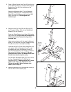
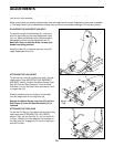
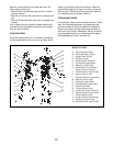
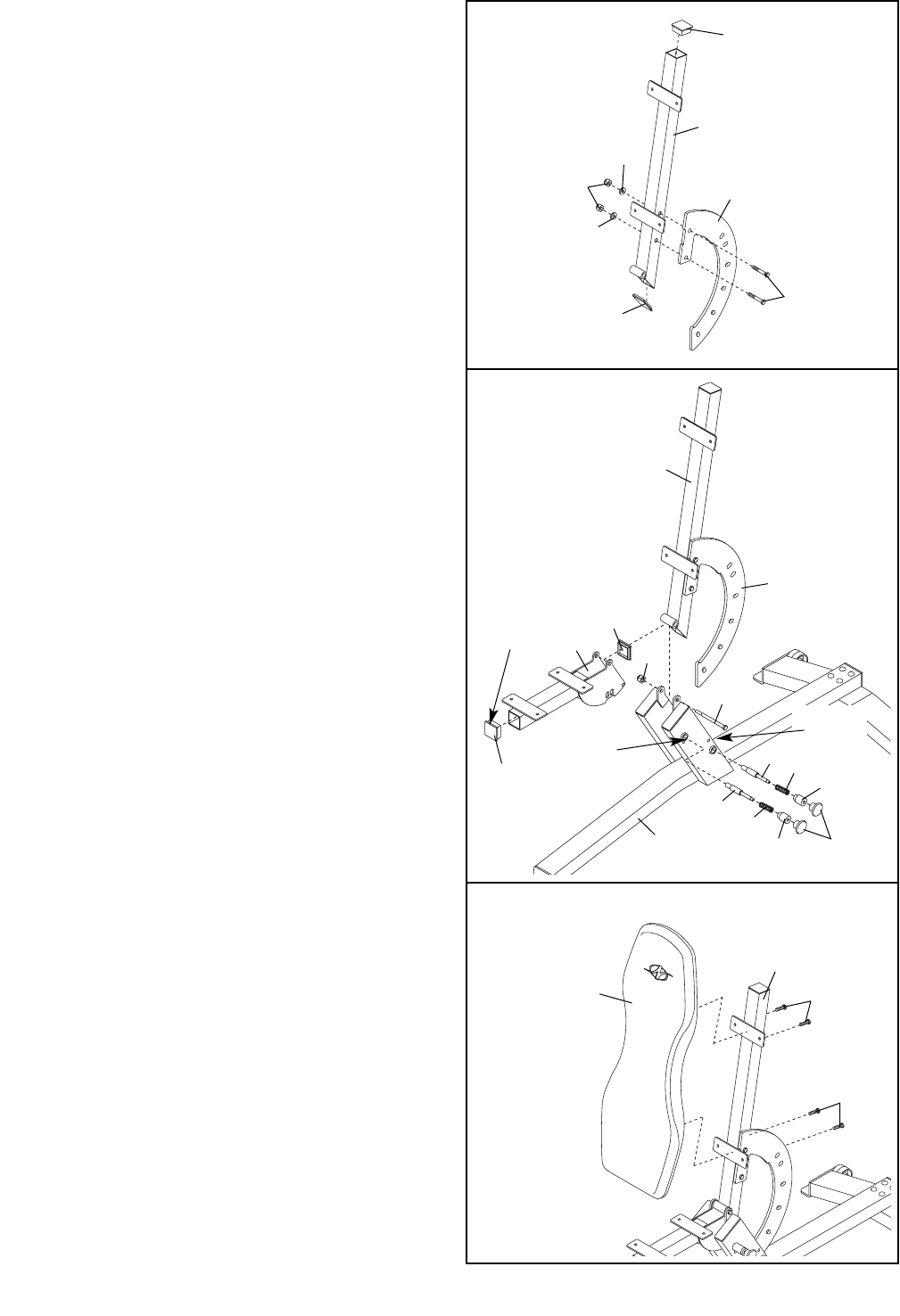
3. Press a 50mm Square Inner Cap (23) into the top
of the Backrest Frame (3). Press a 50mm Square
Angled Inner Cap (43) into the bottom of the
Backrest Frame.
Attach the Adjustment Arm (7) to the Backrest
Frame (3) with two M12 x 77mm Button Head
Bolts (36), two M12 Washers (40), and two M12
Nylon Locknuts (47). Do not tighten the
Locknuts yet.
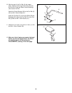
5. Attach the Backrest (4) to the Backrest Frame (3)
with four M6 x 16mm Screws (38).
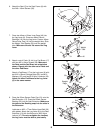
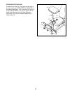
4. Attach the two Pop Pins (28), two Springs (29),
two Threaded Collars (30), and two Adjustment
Knobs (31) to the Frame (1).
Press two 50mm Square Inner Caps (23) into the
Seat Frame (6). Do not press the indicated Cap
all the way into the Frame; this Cap will be
removed later.
Have a second person pull the upper Adjustment
Knob (31) out as far as it will go. Engage the Pop
Pin (28) into a hole in the Seat Frame (6).
Lubricate the M12 x 87mm Button Head Bolt (34)
with grease. With the Adjustment Arm (7) under
the welded rod, attach the Backrest Frame (3)
and the Seat Frame (6) to the Frame (1) with the
Bolt and an M12 Nylon Locknut (47). Do not
overtighten the Locknut; the Backrest and Seat
Frames must be able to pivot easily.
Pull the lower Adjustment Knob (31) out as far as
it will go. Engage the Pop Pin (28) into the
Adjustment Arm (7). Make sure the Pin is in the
center of the hole in the Adjustment Arm.
Tighten the two M12 Nylon Locknuts (not
shown) used in step 3.
3
4
5
28
3
28
30
30
29
29
31
1
Upper
Knob Tube
Do not
press in
fully
3
7
36
40
40
7
47
23
3
34
47
6
23
23
43
38
38
4
Welded
Rod


