


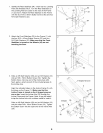
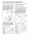
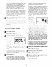

4. The Console (87) requires four "D" batteries (not
included). Alkaline batteries are recommended. To
install batteries, turn the Console facedown and
remove the Battery Cover (84), as shown in the inset
drawing. Insert four batteries into the Console. Make
sure that the negative ends of the batteries
(marked "--") are touching the springs in the
Console. Then, reattach the Battery Cover.
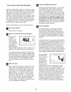
Connect the console wire harness to the Extension
Wire Harness (51). Carefully insert the slack in the
wire harnesses down into the Upright (2).
Attach the Console (87) to the Upright (2) with the four
Console Screws (35) and the four Console Washers
(93) packaged with the Console. Be careful to avoid
pinching the wire harnesses.
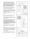
Snap the bookrack onto the Console (87) in the indi-
cated location.
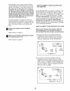
5. Remove the four M10 Nylon Locknuts (26) from the
welded bolts on the front of the Frame (1).
While a second person holds the Upright (2) near the
Frame (1), connect the Extension Wire Harness (51) to
the Wire Harness (85).
Align the four holes in the bracket on the lower end of
the Upright (2) with the welded bolts on the Frame (1).
Lower the Upright, feeding the slack in the
Extension Wire Harness (51) and Wire Harness (85)
into the Upright, until the welded bolts are inserted
into the bracket. Make sure that the Wire Harnesses
are not pinched. Tighten the four M10 Nylon Locknuts
(26) onto the welded bolts.
Adjust the Incline Frame (5) to the desired position
(see HOW TO ADJUST THE INCLINE FRAME on
page 9).
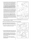
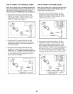
6. Identify the Left Pedal (41). Attach the Left Pedal to the
Left Spring Arm (3) with an M10 x 33mm Carriage Bolt
(61), an M1O Washer (63), and an Adjustment Knob
(77) as shown. Note: The Left Pedal can be attached
in any of five positions (see HOW TO ADJUST THE
PEDALS on page 9).
Attach the Right Pedal (not shown) in the same way.
Make sure that both Pedals are in the same position.
4
84
Wire
Harness.
Make sure the
Wire Harnesses
do not get
pinched and
damaged during
this step.
35 35
Make sure the
Wire Harnesses
(51, 85) do not
get pinched and
damaged during
this step.
\ \ \
Welded Bolts
61
41
7