7
During night and in dusk turn the handle (5) into position
NIGHT. This sets the switching mechanism into position
(4b), when the image intensifier A2 replaces the lens (3) in
the aiming channel. Internal micro switcher SA2 is
connected mechanically with the handle (5).
Now, when you turn the switch SA1 into ON position, the
power from batteries G1 and G2 is applied to the image
intensifier A2. Visible image from the image intensifier
screen (13) is projected onto the reticle (7) and is viewed
through the eyepiece (11) together with the aiming marks.
In twilight, the light filter (1) should be on the objective (2)
for image intensifier protection from light overloads.
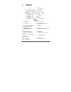
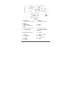
The sight consists of following components: objective (2)
(figure 2) with mounted light filter (1), switching
mechanism (4), eyepiece (14), and interchangeable mount
(17) with fixing mechanism.
The rubber eye shade (16) eases the eye orientation
relatively to sight eye relief, and protects the eye from
recoil. It is fixed on the eyepiece (14) with the clutch (15).


