


Sport and Essential Consumer Treadmills
Incline Motor/Motor Controller Replacement
3
HOW TO…REPLACE THE INCLINE MOTOR OR MOTOR CONTROLLER
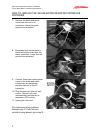
12. Prop up the deck. Use a large hex key in models with a hole in the rail for that
purpose. For other models, place something sturdy under the deck to prevent it from
collapsing during the remainder of this procedure.
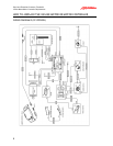
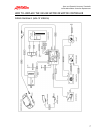
13. Disconnect all wires to the incline motor (see the wiring diagrams on pages 6 and 7.)
14. Disconnect the ground and capacitor
wires from the motor controller board.
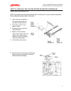
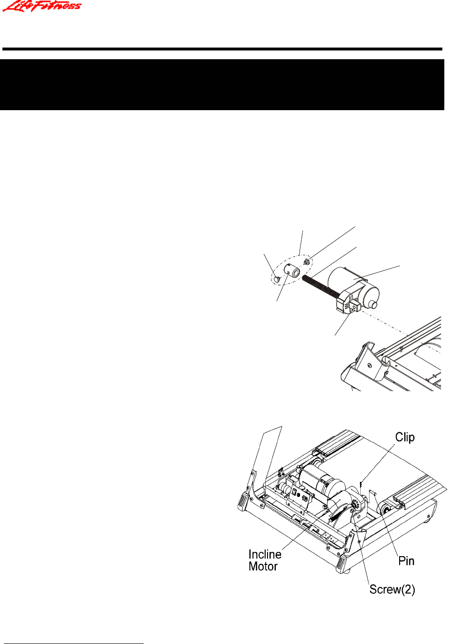
15. Remove the left and right lift nut
screws.
16. Remove the incline motor pin and clip.
17. Remove the incline motor.
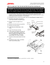
18. Install the new incline motor in the
frame.
19. Insert the incline pin and clip.
20. Incline motors are shipped with the lift
nut at 10%. Adjust the nut location so
that the distance from Adjustment Hole
“A” to Adjustment Hole “B” on the
incline motor is 9¼ inches (235mm).
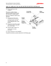
21. Pivot the incline motor toward the front
roller.
22. Reattach the green, black, and white
wires
1
to the incline motor.
1
Incline motor wire configuration: green = ground, black = up, white = common.
Lift Nut
Assembly
Incline
Motor
Left Lift Nut Screw
Right Lift
Nut Screw
Threaded Shaft
Adjustment
Hole “A”
Adjustment
Hole “B”
CAUTION!
After the incline motor lift nut screws are removed in step 15,
the frame is supported only by the nitrogen gas shocks. The treadmill’s
deck can collapse suddenly and must be propped up before proceeding.