


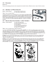
3.5 SEAT ADJUSTMENT AND SEAT BACK PAD
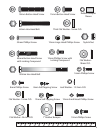
Parts: Hardware Bag #3 (1, 40mm Button Head Screw with Locking Compound)
(1, 24mm Flat Washer)
(1, Rubber Bumper Sleeve)
(1, Rubber Bumper 1”)
(1, 18mm Flat Washer)
(2, 12mm Phillips Screws with Locking Compound)
(2, 12mm Phillips Screws)
(4, 55mm Phillips Screws) R1 Only
(4, 8mm Nylock Nuts) R3 Only
(4, 8mm Self-Tapping Phillips Screws) R3 Only
(4, 12mm Phillips Screws) R3 Only
Tools: 5mm Hex Head Wrench, Phillips Screwdriver, 13mm Socket Wrench
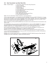
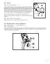
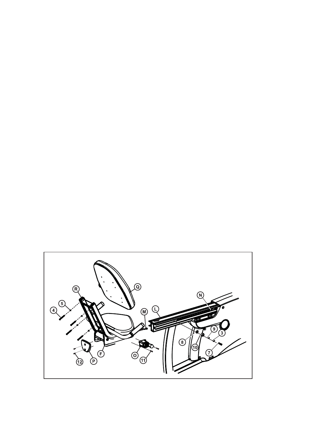
Align the guide rollers located on the underside of the SEAT ASSEMBLY (F) with the SEAT EXTRUSION (L). Carefully
guide the SEAT ASSEMBLY onto the SEAT EXTRUSION. Slide the SEAT ASSEMBLY fully forward. Connect the WIRE
(M) leading from the user left side of the SEAT ASSEMBLY to the JACK located at the left front of the SEAT EXTRU-
SION. Insert the WIRE (M) into the WIRE HARNESS (N) located next to the JACK.
Note: The WIRE (M), JACK and WIRE HARNESS (N) are located on the user left side of the unit. Items shown on the
right for clarity.
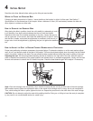
In the hole located on the user right side of the SEAT EXTRUSION (L), behind the SEAT ASSEMBLY (F), install one
40mm BUTTON HEAD SCREW WITH LOCKING COMPOUND (7), one 24mm FLAT WASHER (8), one RUBBER
BUMPER SLEEVE (9), one 1" RUBBER BUMPER (10) and one 18mm FLAT WASHER (3) as shown.
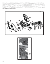
Mount the SEAT ADJUSTMENT LEVER (O) to the user right side of the SEAT ASSEMBLY (F) using two 12 mm
PHILLIPS SCREWS W/LOCKING COMPOUND (11). Tighten the SCREWS securely.
Note: Be sure to mount the SEAT ADJUSTMENT LEVER (O) with the adjustment knob facing upward as shown.
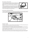
Locate the SEAT EXTRUSION ENDCAP (P). Secure the SEAT EXTRUSION ENDCAP to the SEAT EXTRUSION (L)
using two 12mm PHILLIPS SCREWS (12).
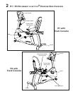
R1 Only: Secure the SEAT BACK PAD (Q) to the UPPER SEAT SUPPORT TUBES (R) using four 55mm PHILLIPS
SCREWS (4) and LOCK WASHERS (5). Tighten the SCREWS securely.
11
R1