STEP 3:
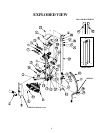
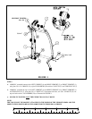
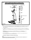
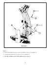
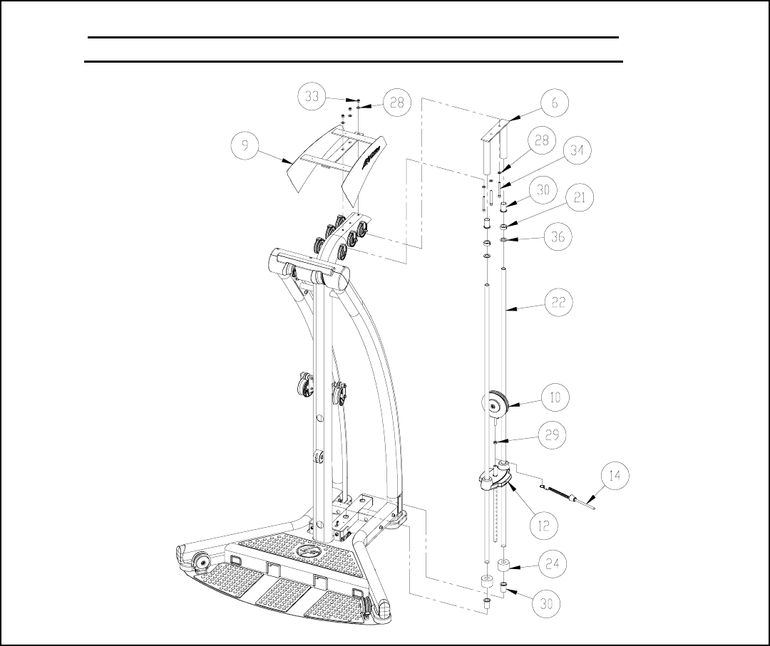
Insert two GUIDE ROD BUSHINGS (30) into bottom of FRONT UPRIGHT (1), slide one CUSHION (24) to bottom of each
GUIDE ROD (22) and insert both GUIDE RODS (22) thru GUIDE ROD BUSHINGS (30) and holes located at bottom of
FRONT UPRIGHT (1)
CAREFULLY slide HEAD PLATE (12) over top of GUIDE RODS (22) followed by two HEAD PLATE BUMPERS (36),
two COLLARS (21), two GUIDE ROD BUSHINGS (30) and position GUIDE ROD BRACKET (6) over top of GUIDE RODS
(22)
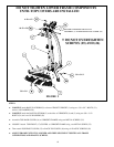
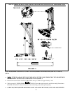
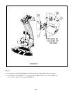
CAREFULLY slide guide rod assembly under top FRONT UPRIGHT (1) and place TOP SHROUD (9) over top of
FRONT UPRIGHT (1) and assemble together using three 3/8 x 3-1/2 BOLTS (34), six 3/8 WASHERS (28)
and three 3/8 NUTS (33).
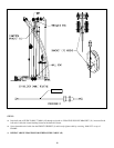
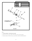
Slide ring of SELECTOR PIN (14) over stem of HEAD PLATE (12) screw HEX NUT (29) onto HEAD PULLEY (10)
then screw HEAD PULLEY (10) into stem of HEAD PLATE (12).
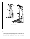
SECURELY TIGHTEN ALL FRAME CONNECTIONS
NOTE:
THREADED SHAFT OF HEAD PULLEY (10) SHOULD BE SCREWED INTO THE STEM APPROXIMATLY 1”
AND HEX NUT SHOULD BE TIGHTENED SECURELY
FIGURE 3
10
3/8 x 3-1/2
TIGHTEN SECURELY
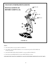
NOTE: REFER TO SHROUD KIT PRIOR TO STARTING STEP 3.
FRONT SHROUD AND BRACKETS MUST BE INSTALLED


