


21
MODELS 91TI, 90T TREADMILLS
TOOLS REQUIRED: Standard Screwdriver, Phillips Screwdriver, Metric Hex Key Set, Side Cutters
NOTE: Proceed with the following steps immediately after attaching the DISPLAY CONSOLE as described in the Assembly
Instructions. Do not install the ACCESSORY TRAYS or PUSH RIVETS.
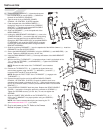
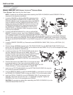
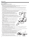
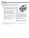
1. Remove the nine SCREWS (a) from the rear of the console securing the FRONT CONSOLE
(b) to the REAR CONSOLE (c). Carefully lift the FRONT CONSOLE. Set the FRONT CON-
SOLE and SCREWS aside.
2. Route the main wire harness (D), POWER CORD (d), and COAXIAL CABLE
(e) through the LARGE CABLE CLIP (f) located at the left inside of the
REAR CONSOLE (c). Route the POWER CORD and COAXIAL
CABLE through the LARGE CABLE CLIP (f) located at the center
inside of the REAR CONSOLE. Continue routing the POWER
CORD and COAXIAL CABLE through the notch at the top of the
REAR CONSOLE.
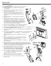
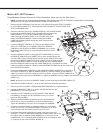
3. Locate the REMOTE CONTROL (g). Configure the REMOTE CON-
TROL for a VERTICAL (C-V) installation. Secure the REMOTE
CONTROL to the left end of the ERGO CROSSBAR (13) as shown.
Be sure the CABLE TIES (C-V) are pulled tight and trim the excess
CABLE TIES.
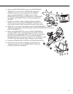
4. Route the REMOTE CABLE (h) along the LEFT HANDLEBAR (1). Secure
the REMOTE CABLE using two CABLE TIES (j) at the locations shown. Be
sure the CABLE TIES are pulled tight and trim the excess CABLE TIES. Route
the remaining REMOTE CABLE through the CABLE CLIP (k) located on the bot-
tom left of the REAR CONSOLE (c) and up through the LEFT ACCESS PANEL.
Route the REMOTE CABLE through the LARGE CABLE CLIP (f) located at the center
inside of the REAR CONSOLE. Continue routing the REMOTE CABLE through the notch at the
top of the REAR CONSOLE.
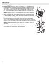
5. Connect the MAIN WIRE HARNESS (D) and HANDLEBAR WIRE HARNESS (B) to the back of
the FRONT CONSOLE (b). With the POWER CORD (d), COAXIAL CABLE (e) and REMOTE
CABLE (h) oriented in the TOP CONSOLE NOTCH as shown, secure the FRONT CONSOLE (b)
using the nine previously removed SCREWS (a). Tighten the SCREWS securely. Replace the ACCESS
PANELS (C).
NOTE: Be careful not to pinch the
REMOTE CABLE (h) when replacing the ACCESS PANELS (C)
.
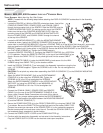
6. Install the ACCESSORY TRAYS (17 & 18) as instructed in the Assembly Instructions.
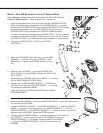
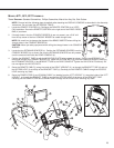
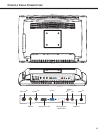
7. Remove the LEFT and RIGHT UPPER HANDLEBAR ENDCAPS (m) and discard them.
8. Position the BRACKET TUBE (n) as shown and slide the ends into the
HANDRAILS (1 & 2) until fully seated.
9. Install the four SET SCREWS (o) into the BRACKET TUBE MOUNT-
ING ARMS (p) and tighten the SET SCREWS securely. Do not over-
tighten the SET SCREWS.
10. Attach the ENTERTAINMENT CONSOLE (q) to the UPPER MOUNT-
ING PLATE (r) using four SCREWS (s) and NYLON WASHERS (t).
Tighten the SCREWS to 6-8 in-lbs. Do not overtighten the SCREWS.
11. Connect the COAXIAL CABLE (e), REMOTE CABLE (h), and POWER
CORD (d) to the rear of the ENTERTAINMENT CONSOLE (q) as shown
under Console Cable Connections at the end of this manual.
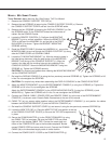
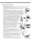
12. Unwrap the MAIN WIRE HARNESS (D) located at the base of the LEFT
UPRIGHT (1). Route the MAIN WIRE HARNESS, POWER CABLE and COAX-
IAL CABLE under the CROSS FRAME MEMBER (E). Connect the 10-PIN
CONNECTOR (10P) of the MAIN WIRE HARNESS to the corresponding JACK
(F) locates at the top of the CONTROL BOARD (G).