


INSTALLATION
18
MODELS 95RI, 93R, 90R RECUMBENT LIFECYCLE
®
EXERCISE BIKES
TOOLS REQUIRED: Metric Hex Key Set, Side Cutters
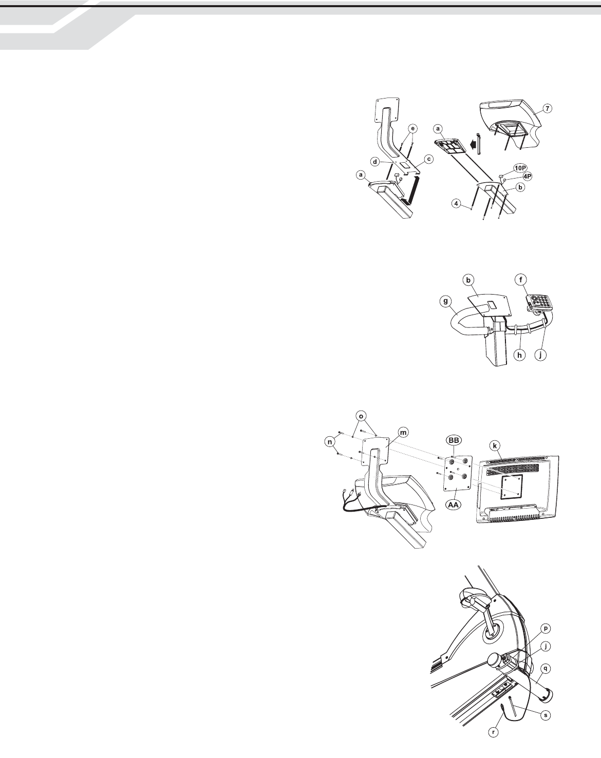
NOTE: Proceed with the following steps before attaching the DISPLAY CONSOLE as described in the Assembly
Instructions.
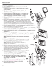
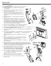
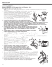
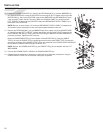
1. Locate the SPACER (a). With the SPACER oriented as shown, feed all the
CONSOLE CONNECTORS, POWER CORD, and COAXIAL CABLE
through the large center hole in the SPACER. Slide the SPACER onto the
CONSOLE MOUNTING PLATE (b) making sure the top of the SPACER
hooks over the top of the CONSOLE MOUNTING PLATE. Align the
mounting holes of the SPACER and CONSOLE MOUNTING PLATE.
Run the POWER CORD, and COAXIAL CABLE through the channel
at the top of the SPACER.
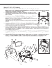
2. Locate the MOUNTING BRACKET (c). With the MOUNTING BRACKET
oriented as shown, feed all the CONSOLE CONNECTORS through the large
center hole in the MOUNTING BRACKET. Align the LOCATING TABS (d) of the MOUNTING BRACKET with the tab
slots and position the MOUNTING BRACKET into the center channel of the SPACER. Slide the MOUNTING
BRACKET upward until it locks solidly in the SPACER. Secure the MOUNTING BRACKET to the SPACER using
two FLAT HEAD SCREWS (e). Tighten the SCREWS securely.
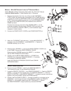
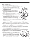
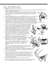
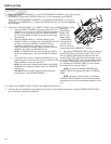
3. Locate the REMOTE CONTROL (f). Configure the REMOTE CONTROL for a VERTICAL
(C-V) installation. Secure the REMOTE CONTROL to the top of the HANDLEBAR (g) as
shown. Be sure the CABLE TIES (C-V) are pulled tight and trim the excess CABLE
TIES.
4. Loop the REMOTE CABLE (h) under the HANDLEBAR (g) and secure it to the HAN-
DLEBAR using three CABLE TIES (j) at the locations shown.
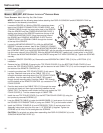
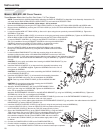
5. Install the DISPLAY CONSOLE (7) as instructed in the Assembly Instructions using the four
new 1-1/2" SCREWS supplied. Tighten the SCREWS to 6-8 in-lbs. Do not overtighten the
SCREWS.
CAUTION: Do not pinch any wires when assembling the DISPLAY CONSOLE (7) to the CONSOLE MOUNTING
PLATE (b).
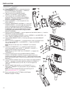
6. Attach the ADAPTER BRACKET (AA) to the ENTERTAINMENT
CONSOLE (k) to the using four SCREWS (BB). Tighten the
SCREWS to 6-8 in-lbs. Do not overtighten the SCREWS.
Attach the ENTERTAINMENT CONSOLE to the UPPER MOUNT-
ING PLATE (m) using four SCREWS (n) and WASHERS (o).
Tighten the SCREWS to 6-8 in-lbs. Do not overtighten the
SCREWS.
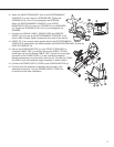
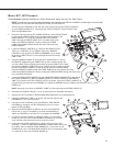
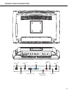
7. Connect the COAXIAL CABLE, POWER CORD and REMOTE
CABLE (h) to the rear of the ENTERTAINMENT CONSOLE (k) as
shown under Console Cable Connections at the end of this manual.
8. CABLE TIE (j) any excess cable together behind the ENTERTAINMENT
CONSOLE (k) and position the cables between the MOUNTING BRACKET
(c) and the DISPLAY CONSOLE (7).
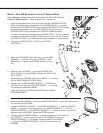
9. Secure the POWER ADAPTER (p) to the FRONT STABILIZER (q) using two CABLE TIES
(j) as shown. Be sure the CABLE TIES are pulled tight and trim the excess CABLE TIES.
Connect the screw-type connector of the POWER CORD (r) to the underside receptacle.
Bundle excess power cord and store under the unit. Connect the COAXIAL CABLE (s) to
the broadcast supply receptacle in similar fashion.
10. Connect the POWER SUPPLY CORD to the POWER ADAPTER (p).
11. Continue with the remainder of assembly as instructed in the Assembly Instructions.
Plug the POWER SUPPLY CORD into an electrical outlet upon completion.