


INSTALLATION
20
MODELS 95XI, 93X, 90X CROSS-TRAINERS
TOOLS REQUIRED: Metric Hex Key Set, Side Cutters, T-45 Torx Wrench
NOTE: Proceed with the following steps before attaching the DISPLAY CONSOLE as described in the Assembly Instructions. Do
not install the left BULLHORN and BULLHORN COVER. Do not install the ACESSORY TRAY.
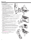
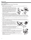
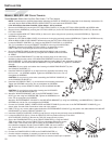
If the left bullhorn has been installed, follow steps 1 & 2 for removal.
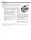
1. Remove the SCREW (22) securing the LEFT BULLHORN COVER (15). Set the LEFT BULLHORN COVER and SCREW aside.
2. Remove the two SCREWS (2) securing the LEFT BULLHORN (13) to the LEFT BULLHORN MOUNTING PLATE (D). Remove the
LEFT BULLHORN.
3. Locate the supplied NEW LEFT BULLHORN (a). Secure it in place using the two previously removed SCREWS (2). Tighten the
SCREWS to 15-20 ft-lbs.
4. Replace the LEFT BULLHORN COVER (15) and secure it using the previously removed SCREW (22). Tighten the SCREW securely.
Slide the BULLHORN COVER GASKET downward to meet the LEFT BULLHORN COVER.
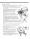
5. Locate the REMOTE CONTROL (b). Configure the REMOTE CONTROL for a HORIZON-
TAL (C-H) installation. Secure the REMOTE CONTROL to the top of the MOUNTING
FINGER (c) located on the NEW LEFT BULLHORN () as shown. Be sure the
CABLE TIES (C-H) are pulled tight and trim the excess CABLE TIES.
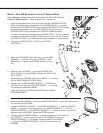
6. Route the REMOTE CABLE (d) through the MONOCOLUMN (H) and up through
the top of the CONSOLE SUPPORT (7) alongside the POWER CORD and COAXI-
AL CABLE.
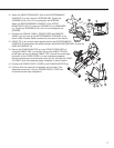
7. Locate the MOUNTING BRACKET (e). With the mounting holes in the tube facing
downward, slide the tube portion of the MOUNTING BRACKET into the top of the CON-
SOLE SUPPORT (7). Align the inserts in the tube with the mouting holes on the underside of the CON-
SOLE SUPPORT. Secure the MOUNTING BRACKET using two SCREWS (f). Tighten the SCREWS
securely.
CAUTION: Do not to pinch and cables when inserting the MOUNTING BRACKET (e) into
the CONSOLE SUPPORT (7).
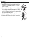
8. Install the DISPLAY CONSOLE (4) as instructed in the Assembly Instructions using
the four new 1-1/2" SCREWS supplied. Tighten the SCREWS to 6-8 in-lbs. Do not
overtighten the SCREWS.
CAUTION: Do not pinch any wires when assembling the DISPLAY CONSOLE (4)
to the CONSOLE SUPPORT (7).
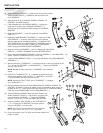
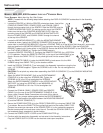
9. Install the ACCESSORY TRAY (17) as instructed in the Assembly Instructions.
Tighten the SCREWS to 6-8 in-lbs. Do not overtighten the SCREWS.
NOTE: Feed any excess REMOTE CABLE (d) into the MONOCOLUMN
(H).
CAUTION: Do not pinch any wires when inserting the ACCESSORY
TRAY (17) into the MONOCOLUMN (H).
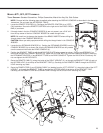
10. Attach the ADAPTER BRACKET (AA) to the ENTERTAINMENT CON-
SOLE (g) to the using four SCREWS (BB). Tighten the SCREWS to 6-8
in-lbs. Do not overtighten the SCREWS.
Attach the ENTERTAINMENT CONSOLE to the MOUNTING BRACKET (e) using four SCREWS (j) and WASHERS (k). Tighten the
SCREWS to 6-8 in-lbs. Do not overtighten the SCREWS.
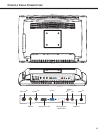
11. Connect the COAXIAL CABLE, POWER CORD and REMOTE CABLE (d) to the rear of the ENTERTAINMENT CONSOLE (g) as
shown under Console Cable Connections at the end of this manual.
12. CABLE TIE (m) any excess cable together behind the ENTERTAINMENT CONSOLE (g) and position the cables between the MOUNT-
ING BRACKET (e) and the DISPLAY CONSOLE (4).
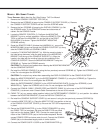
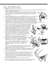
13. Install the CONSOLE SUPPORT COVER (8) and secure it using the two previously removed SCREWS (2).
14. Locate the NEW TOP CAP (n). Place the NEW TOP CAP into position at the top of the CON-
SOLE SUPPORT COVER (8). Be sure the TOP CAP snaps securely in place.
15. Secure the POWER ADAPTER (o) to the FRONT STABILIZER (p) using two CABLE
TIES (m) as shown. Be sure the CABLE TIES are pulled tight and trim the excess
CABLE TIES. Connect the screw-type connector of the POWER CORD (q) to
the underside receptacle. Bundle excess POWER CORD and store under the
unit. Connect the COAXIAL CABLE (r) to the broadcast supply cable in simi-
lar fashion.
16. Connect the POWER SUPPLY CORD to the POWER ADAPTER (o).
17. Continue with the remainder of assembly as instructed in the Assembly
Instructions. Plug the POWER SUPPLY CORD into an electrical outlet upon completion.