


INSTALLATION
24
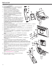
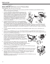
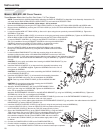
7. Attach the ADAPTER BRACKET (n) to the ENTERTAINMENT CONSOLE (o) to the using four
SCREWS (p). Tighten the SCREWS to 6-8 in-lbs. Do not overtighten the SCREWS.
Attach the ENTERTAINMENT CONSOLE to the MOUNTING BRACKET (q) using four
SCREWS (r) and WASHERS (s). Tighten the SCREWS to 6-8 in-lbs. Do not overtighten
the SCREWS.
8. Connect the COAXIAL CABLE (m), REMOTE CABLE (j) and POWER CORD (l) to the
rear of the
ENTERTAIN-
MENT CON-
SOLE (o) as
shown under
Console Cable
Connections at
the end of this
manual. Feed any
excess cable into the BRACKET TUBE (e).
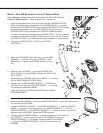
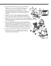
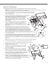
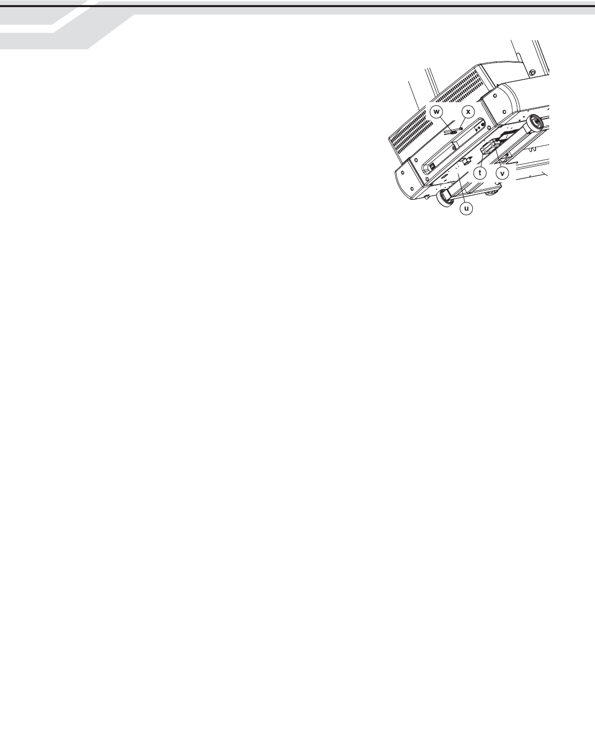
9. Mount the POWER ADAPTER (t) to the bottom of
the MOTOR PAN (u) using two CABLE TIES (v). Be
sure the CABLE TIES are pulled tight and trim the
excess CABLE TIES. Connect the screw-type connec-
tor of the POWER CORD (w) to the underside recepta-
cle. Bundle excess power cord and store under the
unit. Connect the COAXIAL CABLE (x) to the broad-
cast supply cable in similar fashion.
NOTE: Be sure the POWER ADAPTER and
CABLE TIES do not interfere with the LIFT MECHA-
NISM.
NOTE: Be sure to leave at least 12” of excess
COAXIAL CABLE between the floor and the coaxial
connection on the unit to accomodate elevation of the
unit.
10. Connect the POWER SUPPLY CORD to the POWER ADAPTER (t).
11. Continue with the remainder of assembly as instructed in the Assembly Instructions. Plug the POWER SUPPLY CORD
into an electrical outlet upon completion.
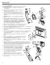
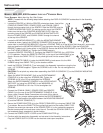
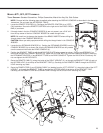
3. Route the REMOTE CABLE (c) along the inside of the LEFT
UPRIGHT (1), up through the CABLE GUIDE (d), through the
CABLE CLIPS (a) and out the top of the REAR CONSOLE
(R). Route the REMOTE CABLE around the console stand-
offs as shown.
4. With the POWER CORD (e), COAXIAL CABLE (f) and
REMOTE CABLE (c) oriented in the TOP CONSOLE NOTCH
as shown, connect the CONSOLE CONNECTORS as
instructed in the Assembly Instructions and secure the
FRONT CONSOLE (S) using the eight previously removed
SCREWS (Q). Tighten the SCREWS securely.
NOTE: All CABLES should be routed throught the CABLE
GUIDE (c) located at the lower left of the REAR CONSOLE
(R).
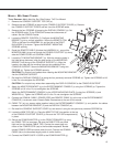
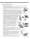
5. If through-holes in the four CONSOLE BOSSES (g) are not
present, use a 5/16” drill from the top center of the four CON-
SOLE BOSSES to create through-holes.
NOTE: Be careful not to damage the threads of the BRASS
INSERTS when drilling the through-holes in the CONSOLE
BOSSES (g).
CAUTION: Wear eye safety equipment when drilling the
through-holes in the CONSOLE BOSSES.