


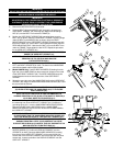
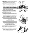
9. (Model 9000HR Only) With the left side of the DISPLAY CONSOLE (#4)
supported, carefully route the HEART RATE WIRE HARNESS (B)
through the right side access hole of the DISPLAY CONSOLE.
10. (Model 9000HR Only) While pulling the USER RIGHT UPRIGHT (#2)
slightly outward, carefully lower the DISPLAY CONSOLE (#4) onto the
USER RIGHT UPRIGHT. Secure the DISPLAY CONSOLE to the
UPRIGHTS using four SCREWS (#5). Tighten the SCREWS securely.
(Model 8500 Only) Lower the DISPLAY CONSOLE (#4) onto the USER
RIGHT UPRIGHT (#2). Secure the DISPLAY CONSOLE to the
UPRIGHTS using four SCREWS (#5). Tighten the SCREWS securely.
CAUTION: BE CAREFUL NOT TO PINCH THE WIRE HARNESS (D).
MISE EN GARDE : VEILLEZ À NE PAS PINCER LE FAISCEAU (D).
11. Secure the bottom of the DISPLAY CONSOLE (#4) to the inside of the
UPRIGHTS (#1 & #2) using two PUSH RIVETS (#6).
12. Connect all WIRE HARNESS CONNECTORS to their corresponding
JACKS located within the rear access holes. Feed excess WIRE
HARNESS into the DISPLAY CONSOLE (#4). Replace REAR PANEL
ACCESS DOORS (C) as necessary.
13. Tighten all BOLTS and SCREWS securely.
14. Insert the ACCESSORY TRAYS (#17 & #18) into the DISPLAY
CONSOLE (#4) as shown. Press downward firmly until the ACCESSORY
TRAYS snap securely into place.
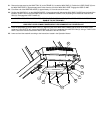
15. Unwrap the MAIN WIRE HARNESS (D) located at the base of the USER
LEFT UPRIGHT (#1). Route the MAIN WIRE HARNESS under the
CROSS FRAME MEMBER (E). Connect the 10-PIN CONNECTOR (10P)
of the MAIN WIRE HARNESS to the corresponding JACK (F) located at
the top of the CONTROL BOARD (G).
16. Replace the MOTOR COVER. Secure the MOTOR COVER using four
MOUNTING SCREWS (#9).
CAUTION: BE SURE THE MOTOR COVER IS OUTSIDE ALL
MOUNTING TABS.
MISE EN GARDE : SOYEZ SÛR QUE LA COUVERTURE DU MOTEUR
COUVRE TOUTES LES PARENTHÈSES.
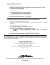
17. Using two MOUNTING SCREWS (#9) each, secure the four FRAME
ENDCAPS (#12) to the four FRAME (A) corners.
NOTE: THE LARGER END OF THE FRAME ENDCAPS (#12) SHOULD
FACE THE CENTER OF THE TREADMILL.
ATTENTION: LA FIN PLUS GRANDE D'ENDCAPS (# 12) DEVRAIT
FAIRE FACE AU CENTRE DU TAPIS ROULANT.
18. Install the two REAR ROLLER GUARDS (#15 & #16) as shown using one
MOUNTING SCREW (#9) each.
19. Using a rubber mallet, install the four HANDRAIL ENDCAPS (#14).
Model 9000HR and International 8500 Only
20. Move the treadmill into the desired location for use. Plug the linecord into
a dedicated NEMA R5 (U.S. only) electrical outlet. Turn the power on at
the ON/OFF switch located at the front of the treadmill. Using the UP
INCLINE ARROW KEY, raise the treadmill to its maximum elevation
(15%). Unplug the treadmill from the electrical outlet.
1
DE
F
10P
G
17
4
5
1
2
5
B
D
6
18
C
9
16
15
A
12
9
9
12
9