


IMPORTANT!
DO NOT DISCARD THE SHIP KIT LOCATED ON TOP OF THE DECK AND
BELT. ALL NECESSARY COMPONENTS NEEDED TO COMPLETE THE
INSTALLATION ARE LOCATED IN THE SHIP KIT.
IMPORTANT!
NE JETEZ PAS LE KIT D’EXPÉDITION PLACÉ SUR LE DESSUS DU
PLATEAU ET SUR LE TAPIS. IL CONTIENT TOUS LES ÉLÉMENTS
NÉCESSAIRES POUR L’INSTALLATION.
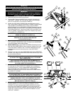
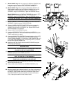
1. Remove the MOTOR COVER and set aside.
2. Feed one BOLT (#3) and WASHER (#10) through the forward most
USER RIGHT UPRIGHT (#2) mounting hole. Begin hand threading a
NUT (#7) onto the BOLT from under the FRAME (A).
3. Position the USER RIGHT UPRIGHT (#2) mounting flange near the
BOLT (#3) as shown. Slide the USER RIGHT UPRIGHT mounting flange
under the BOLT and WASHER (#10) as shown. Align the REAR
MOUNTING HOLE of the USER RIGHT UPRIGHT mounting flange with
that of the FRAME (A). Insert a BOLT (#3) and WASHER (#10) onto the
REAR MOUNTING HOLE. Hand thread a NUT (#7) onto the BOLT from
under the FRAME. Finger tighten the two NUTS. Repeat the procedure
for the USER LEFT UPRIGHT (#1).
NOTE: BE SURE NOT TO DAMAGE THE MAIN WIRE HARNESS
UNDER THE USER LEFT UPRIGHT (#1).
ATTENTION: SOYEZ SÛR DE NE PAS ENDOMMAGER LE HARNAIS
PRINCIPAL DE FIL SOUS LA MAIN GAUCHE
D'UTILISATEUR RAIL(#1).
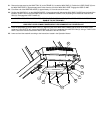
4. Locate the HANDLEBAR (#13). Position the HANDLEBAR between the
LEFT and RIGHT UPRIGHTS (#1 & #2). The bend in the HANDLEBAR
should face upward and tilt slightly forward.
5. (Model 9000HR Only) Feed the WIRE HARNESS (B) leading from the
right end of the HANDLEBAR into the access hole located on the inside
of the USER RIGHT UPRIGHT (#2). The WIRE HARNESS should be
routed forward and out the side access hole of the USER RIGHT
UPRIGHT.
6. Secure the user right end of the HANDLEBAR (#13) to the USER RIGHT
UPRIGHT (#2) using one HANDLEBAR MOUNTING SCREW (#8). Leave
the screw loose at this time.
NOTE: BE CAREFUL NOT TO DAMAGE THE MAIN WIRE HARNESS
(B) WHEN ATTACHING THE HANDLEBAR (#13) TO THE USER
RIGHT UPRIGHT (#2).
NOTE: FAITES ATTENTION À NE PAS ENDOMMAGER LE
HARNAIS PRINCIPAL DE FIL (B) EN ATTACHANT LE GUIDON (#
13) AU RAIL DROIT D'UTILISATEUR (# 2).
7. Insert the remaining HANDLEBAR MOUNTING SCREW (#8) through
the mounting hole of the USER LEFT UPRIGHT (#1). Position the
grounding spring (#11) over the HANDLEBAR MOUNTING SCREW.
Align the left side of the HANDLEBAR with the HANDLEBAR
MOUNTING SCREW. Secure the user left end of the HANDLEBAR to
the USER LEFT UPRIGHT.
NOTE: BE CAREFUL NOT TO DAMAGE THE MAIN WIRE HARNESS
(D) WHEN INSERTING THE HANDLEBAR MOUNTING SCREW (#8)
INTO THE MOUNTING HOLE OF THE USER LEFT UPRIGHT (#1).
ATTENTION: FAITES ATTENTION À NE PAS ENDOMMAGER LE
HARNAIS PRINCIPAL DE FIL (D) EN INSÉRANT LA VIS DE
SUPPORT DE GUIDON (# 8) DANS LE TROU DE SUPPORT DE LA
MAIN GAUCHE D'UTILISATEUR RAIL(#1).
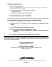
8. Locate the DISPLAY CONSOLE (#4). Remove the REAR PANEL
ACCESS DOORS (C). Position the DISPLAY CONSOLE over the
UPRIGHTS (#1 & #2). Route the MAIN WIRE HARNESS (D) leading
from the top of the USER LEFT UPRIGHT (#1) through the left side
access hole of the DISPLAY CONSOLE and out the user left rear panel
access hole. Lower the left side of the DISPLAY CONSOLE onto the
USER LEFT UPRIGHT.
3
10
2
7
A
2
1
13
B
8
8
11
D
B
17
4
5
1
2
5
B
D
6
18
C