


13
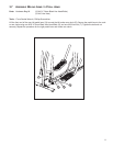
3.9 CONNECT ALL CONSOLE WIRING; CONSOLE TO CONSOLE BRACKET;
B
ACK PLASTIC SHELL
Parts: Hardware Bag #6 (4, M5 X 12mm Silver Phillips Screws)
Tools: Phillips Screwdriver
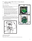
Position the console (Z) close to the console bracket (W) and follow
the below instructions to connect all wiring.
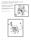
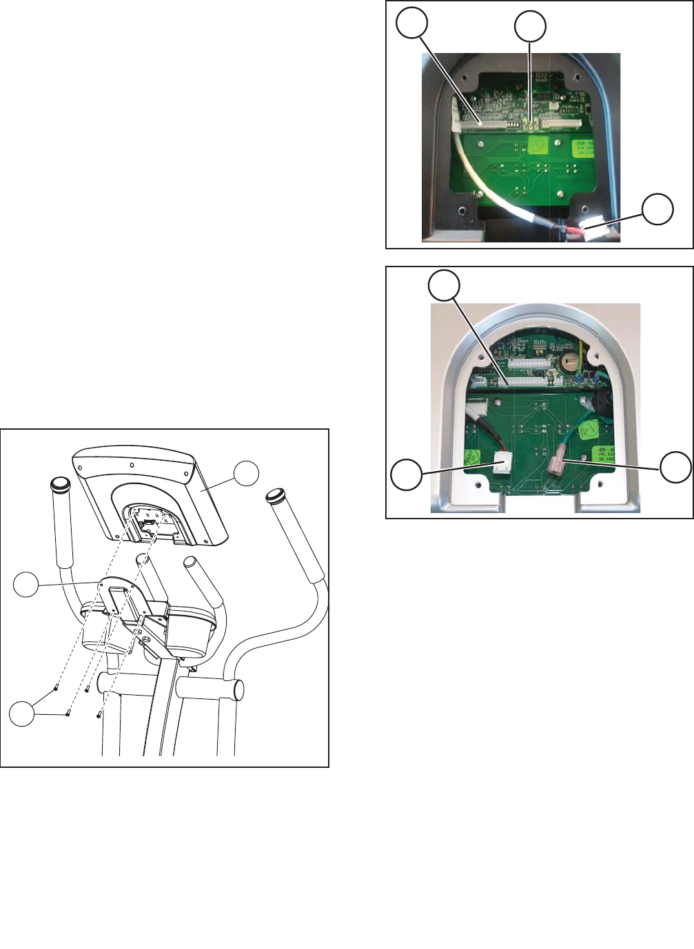
Plug cables into the back of the display console:
1. Plug the 15-pin connector at the end of the upper wire harness
into the 15-pin connector (15P) in the back of the display
console. Make sure the connector snaps into place.
2. Plug the 4-pin connector at the end of the contact heart rate
sensor cable to the 4-pin cable (4P) located in the console.
3. Plug the ground cable (green wire, single spade) from the
product base to any of the three metal ground terminals (G) in
the Go Console, or into the connector (G) leading from the
back of the Track Console.
4. Push excess cables into the opening of the upright tube
assembly.
Line up the four holes in the console bracket with the four holes in
the back of the display console. Attach the display console using four
M5 X 12mm Silver Phillips Screws (A). Be careful not to pinch cables
between the console and the console bracket. Be sure to get each
screw started before fully tightening.
Note: To avoid stripping, do not overtighten the screws.
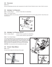
3.10 PLUG IN THE UNIT
Parts: Electric Transformer
Plug the black cord into the back of the machine and into a household electrical outlet.
4P
15P
G
W
A
Z
4P
15P
G
Go Console
Connections
Track Console
Connections