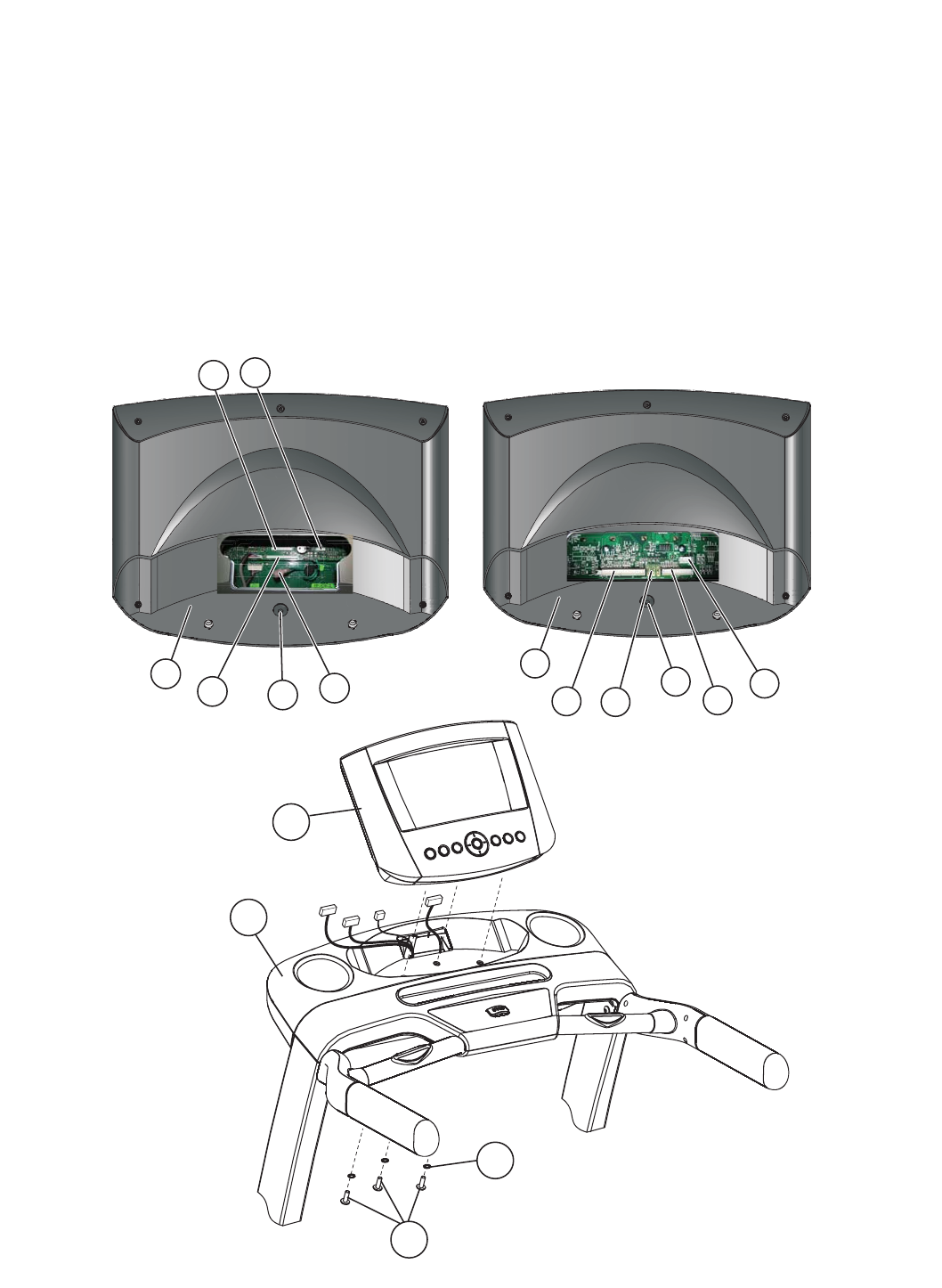
3.4 INSTALLING THE CONSOLE
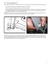
Remove the pre-installed bolt (A) from the back of the main console (B). Position the main console near the top of the
console bridge and attach the connectors leading from the console bridge to the corresponding tabs on the back of the
main console. The main console harness (C) is the largest connector. The Activity Zone harness (D) is the mid-size con-
nector. The grounding wire (E) is the small green and yellow wire that inserts onto any of the three metal circuit board
receptacles on the Go Console or to the connector leading from the back of the Track Console. The safety switch con-
nector (F) is the 5-Pin connector. Be sure the connectors are fully seated together. Feed any excess wire into the con-
sole bridge.
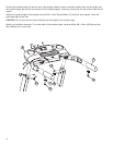
Attach the main console to the console bridge using three M8 x 25mm BOLTS (6) and three STAR WASHERS (3). Tighten
the bolts securely.
CAUTION: Do not pinch the wires when attaching the main console to the console bridge.
Securely tighten all the bolts that were left finger-tight.
11
B
C
E
A
D
F
B
5
6
3
B
A
D
C
F
E
Track Console Connection
Go Console Connection


