


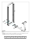
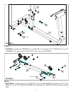
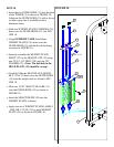
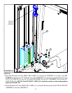

• LOOSELY assemble the TOP BOOM (2) to the TOWER (3) and the UPRIGHT (5) using four 1/2 X 4”
BOLTS (18), four 1/2” WASHERS (24), and three 1/2” LOCK NUTS (26) as shown in FIGURE 4.
STEP 4
FIGURE 4
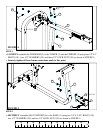
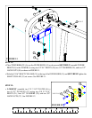
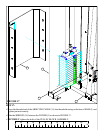
• SECURELY assemble SEAT SUPPORT (6) to the BASE (1) using two 1/2 X 2-3/4” BOLTS (19),
two 1/2” WASHERS (24), and two 1/2” LOCK NUTS (26) as shown in FIGURE 5.
STEP 5:
FIGURE 5
18 1/2 X 4”
26
24
3
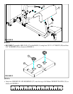
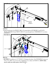
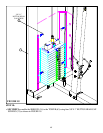
• Securely tighten all loose frame connections made to this point.
1
2
5
26
24
1/2 X 4” 18
6
0
1
2
3 4 5
6
1/2 1/2 1/2 1/2 1/2 1/2
6
19 1/2 X 2-3/4”
26
24
29