13
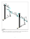
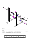
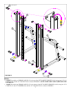
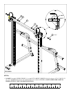
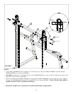
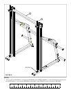
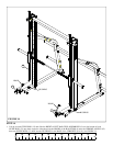
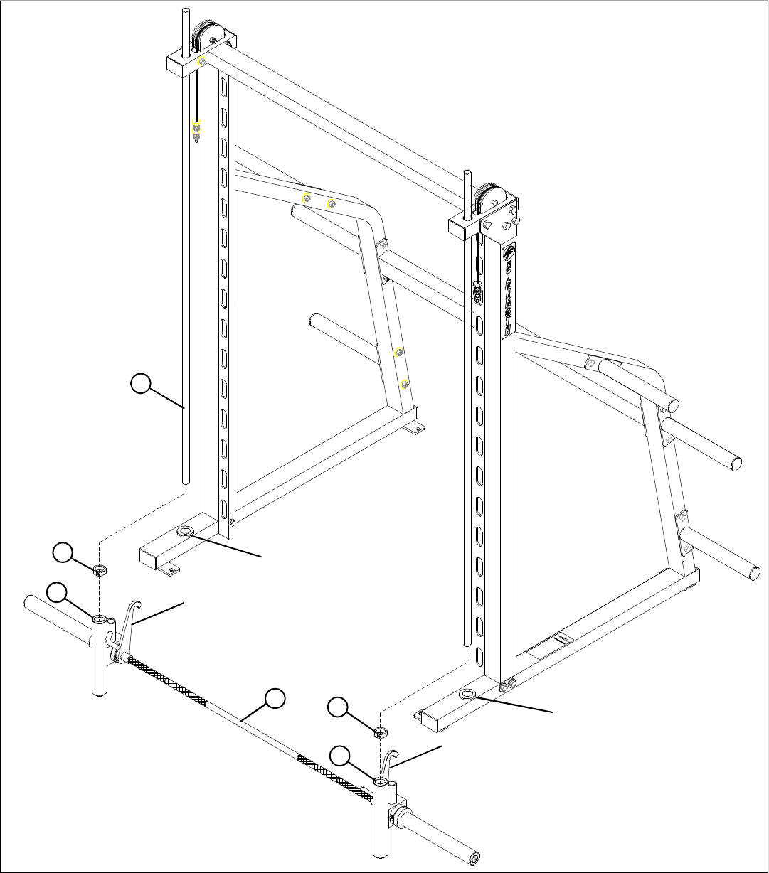
FIGURE 13
STEP 13:
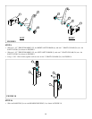
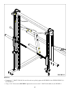
• Lift up each GUIDE ROD (13) and insert them through each BEARING HOUSING (1) on the SMITH BAR ASSEMBLY (7)
then seat GUIDE RODS (13) back into the BUSHINGS in the BASE of the UPRIGHTS (9 & 10). See FIGURE 13.
7
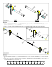
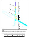
• Lift up each GUIDE ROD (13) and slide one 1” SHAFT COLLAR (24) over the bottom of each GUIDE ROD (13). Position 1”
SHAFT COLLAR (24) half way up the GUIDE ROD (13) and tighten it using a 3/16” Allen wrench. See FIGURE 13.
1
HOOK
1
HOOK
BUSHING
BUSHING
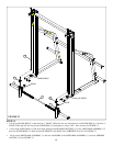
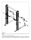
• Lift up on the SMITH BAR ASSEMBLY (7) and lock the HOOKS of the SMITH BAR ASSEMBLY (7) onto the CHROME
ANGLES (12). See FIGURE 13.
24
24
13


