


|o
o
4o "
’7.
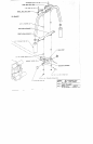
FACTOR 525 PEC DEC ATT. ASSEMBLY INSTRUCTIONS (LEVEL 2)
__
LOOSEN the 3/8 X 4 1N. BOLT that ~ssembles the two (2) PULLEYS, and two (2) I/2 IN. SPACERS
the BASE directly behind the FRONT UPRIGHT. Remove the 3/8 IN. LOCK NUT, and the 3/8 IN.
WASHER.. Slide the BOLT out enough to remove the two (2) 1/2 IN. SPACERS. Replace if.it I/2 IN.
SPACERS with one (I) .~-I~ X I IN. PULLEY, as shown in (VIEW B-B). Slide BOLT back
Replace the 3/8 IN. WASHER., and 3/8 IN. NUT. TIGHTEN CONNECTION SECURELY.
SECURELY assemble one (I) 4-I/2 X 1 IN. PULLEY to the single hole in the BASE directly behind the
FRONT UPRIGHT as shown in (VIEW B-B) on drawing, using one (I) 3/8 X I-3/4 IN. BOLT, two
3/8 IN. WASHERS, and one (1) 3/8 IN. LOCK NUT.
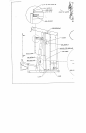
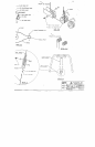
To assemble the LOOP CABLE, follow the cable routing diagram on drawing, and use the following
steps:
Assemble one end of the LOOP CABLE to the LEFT ARM ADVANCE and the other cad ofthe
LOOP CABLE to the RIGHT ARM ADVANCE (MAKE SURE THAT LOOP CABI3E IS
ROUTED BETWEEN THE AB CRUNCH CABLE AND THE FRONT UPRIGHT) as shown
on drawing, using~.wo (2) 318 IN. NUT, four (4) 3/8 IN. WASHERS, and two (2) 3/8 IN.
HEIGItT LOCK NUT. (TIGHTEN THE CONNECTION ENOUGH TO REMOVE ’rile
PLAY, YET AL].,OWING THE LOOP TO MOVE FREELY)
¯
Drape the CABLE over the both PULLEYS on the CENTER PULLEY BI~.CKET. (THIS
WILL FORM A LOOP IN THE CENTER OF THE CABLE)
¯
Position CABLE RETAINING CLIPS in a 45 DEGREE position over the PULLEYS and
CABLES, and tighten the two (2) PULLEY connections SECURELY. SEE DRA’~/ING.
To assemble the LINK CABLE, follow the cable routing diagram on drawing, and use the iblt~wing steps:
®
LOOSELY assemble the PULLt:Y BRACKET to the LINK CABLE as shown in (DE’.[’AIL E)
drawing, using two (2) I/4 IN. WASI-tER, and two (2) 1/4-28 IN. NUTS. (LOCATE PULLEY
BRACKET HALF WAY UP ONTItETItREADSOFTHELINKCABLE" DO NOT
TIGHTEN NUTS AT TItlS TIME)
,,
Slip one (1) 4-1/2 X I IN. PULLEY into the LOOP ofthe LOOP CABLE created from routing
STEP 3. (VIEW D-D) While holding fl~at PULLEY in the LOOP, SECURELY assemble the
PULLEY BtL4.CKET over the PULLEY as shown in (DETAIL E) on drawing, using one (1) 318
2 IN. BOLT, two (2) 3,’8 IN. \VASI-I~RS, and one (I) 3~8 IN. LOCK
¯
Route the LINK CABLE as shown on drawing. (ALSO SEE VIEW B-B)
o
Run the LINK CABLE through the pre-deterrnined hole of ~he D-RING as shown in (’.DETAIL A)
and attach one (I) D-RING CABLE CLIP around the ball end of the LINK CABLE.
Attach one (I) SHOCK CORD to the D-RING CABLE CLIP on the end of the LINK CABLE as shovrn
in (DETAIL A).
Route the SHOCK CORD up and around the: pro-determined 2 IN. PULLEY above the D-RING as shown
in (VIEW C-C). and down ~o the BASE.
Attach one (1) SWIVEL to the end of the SHOCK CORD. Slip ti;e end of the SWIVEL over the L-PIN
on the BASE, and position the SWIVEL directl: over the FIRST PULLEY as shown in (VIEW B-B)
drawing.
oO