


701
FACTOR 525 PEC DEC ATT. ASSEMBLY INSTRUCTIONS
NOTE:
o
(LEVEL 1)
IF THE SHROUD IS ASSEMBLED TO THE FACI’OR 525, IT WILL NEED TO BE REPdOVED
TO ASSEMBLE THE PEG DEC ATTACHMENT. PLEASE REMOVE THE SHROUD AT THIS
TIME BY CAREFULLY REMOVING TIIE FOURTEEN (14) SHROUD FASTENEFKg.
10.
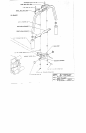
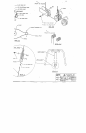
Insert two (2) 2 IN. SQ. END CAPS into both ends of the BEARING HOUSING, as shown on drawing.
SECURELY assemble the BEARING HOUSING and the CENTER PULLEY BRACKET to the
FRONT UPRIGHT as shown on drawing, using p, vo (2) I/’2 X 4-1/2 IN. BOLTS, four (4) I~
WASHERS, and two (2) I/2. IN. LOCK NUTS. (TttE CONNECTOR PLATES ON THE BEARING
HOUSING AND THE CENTER PULLEY BRACKET HAVE SLOTTED HOLES. SHIFT THE
BEARING HOUSING DOWN AND THE CENTER PULLEY BRACKET UP AS FAR AS
POSSIBLE)
¢°
Insert four (4) 2 IN. SQ. END CAPS into BOTH ENDS of the LEFT, and RIGHT PEC DEC ARMS
shown on drawing.
Assemble one (1) 3/4 IN: WASHER, and the LEFT ARM .a DVANCE to the LEFT PEC DEC ARM
shown on drawing. Also Assemble one (1) 3/4 IN. WASI l[’2t~., :,,td the RIGHT ARM ADVANCE to the
RIGHT PEC DEC ARM as shown.
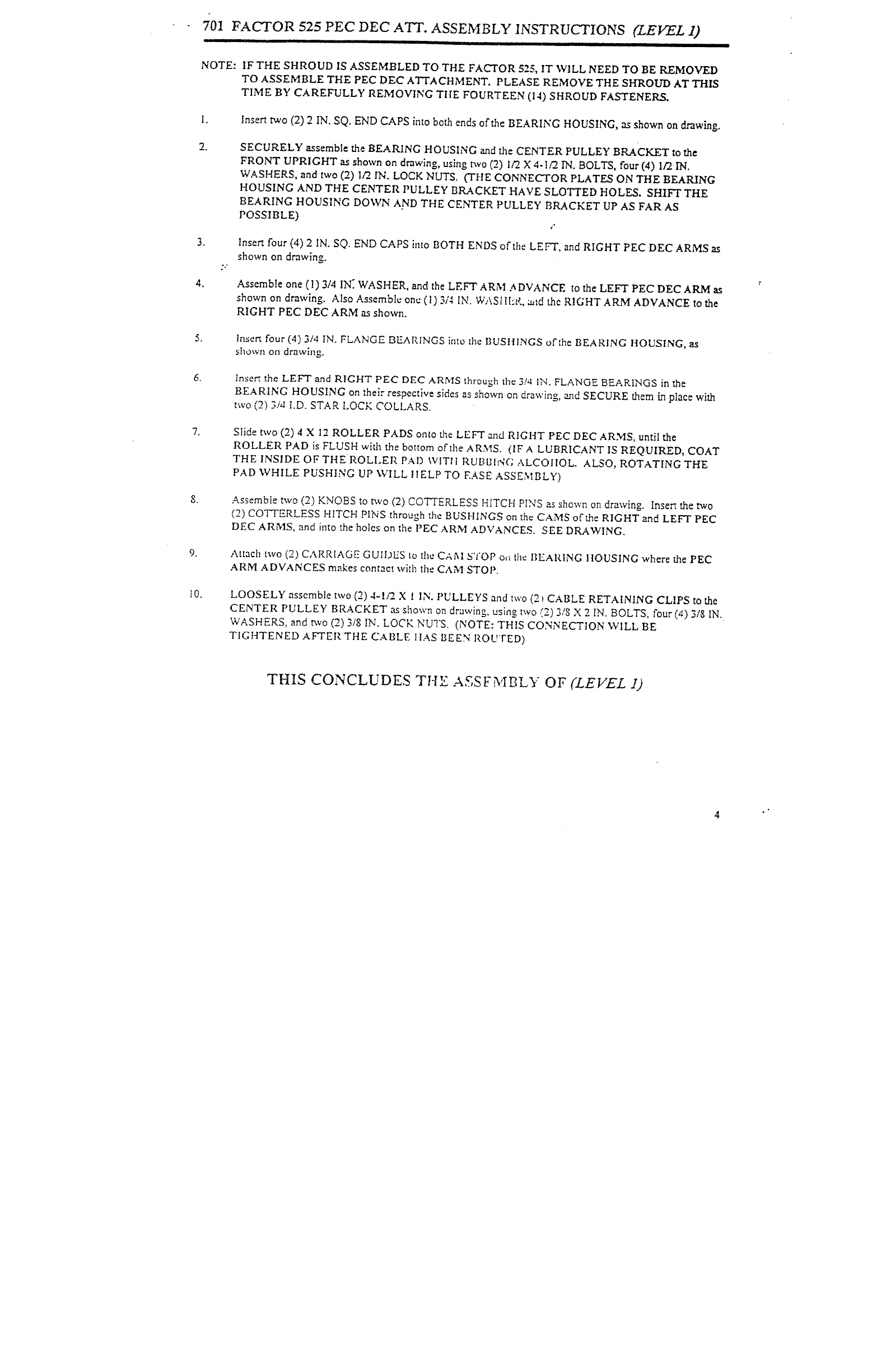
Insert four (4) 3/4 IN. FLANGE BEARINGS into {he BUSHINGS of the BEARING HOUSING,
shown on drawing.
Insert the LEFT and RIGHT PEC DEC ARMS through the 3/4 IN. FLANGE BEARINGS in the
BEARING HOUSING on their respective sides as shown on drawing, ~d SECURE them in place with
two (2) 3/d I.D. STAR LOCK COLLARS.
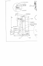
Slide two (2) 4 X 12 ROLLER PADS onto the LEFT and RIGHT PEC DEC ARMS, until the
ROLLER PAD is FLUSH with the bottom or’the ARMS. (IF A LUBRICANT IS REQUIRED, COAT
THE INSIDE OF THE ROLLER PAD WITII RUBIJINC ALCOIIOL. ALSO, ROTATING THE
PAD WHILE PUSHING UP ’,VILL I lELP TO EASE ASSEMBLY)
Assemble t~vo (2) KNOBS to two (2) COTTERLESS HITCH PINS as shown on drawing. Insert the
(2) co’r-FERLESS HITCH PINS through the BUSHINGS on the CAMS of the RIGHT and LEFT PEC
DEC ARMS, and into the holes on the PEC ARM ADVANCES. SEE DRAWING.
Attach two (2) CAP.RIAGE GUll)US to the CA~I STOP o,~ the IIEARING I1OUSING where the
ARM ADVANCES makes contact with the CANt STOP.
LOOSELY assemble txvo (2) 4-1/2_ X IN. PULLEYS and ~wo (2 ) CABLE RETAINING CLIPS to the
CENTER PULLEY BRACKET as shown on drawing, using two (2) 3/8 X 2 IN. BOLTS, four (4) 3/8
WASHERS, and two (2) 3/8 IN. LOCK NUTS. (NOTE: THIS CONNECTION WILL
TIGHTENED AFTER THE CABLE ttAS BEEN ROUTED)
THIS CONCLUDES THE ASSFMBLY OF (LEVEL