


E25 / E55 Elliptical
5
UNPACKING THE UNIT
1. Using a razor knife (Box Cutter) cut the outside, bottom, edge of box along the dotted
Line. Lift Box over the unit and unpack.
2. Carefully remove all parts from carton and inspect for any damage or missing parts. If
damaged parts are found, or parts are missing, contact your dealer immediately.
3. Locate the hardware package. The hardware is separated into steps. Remove the tools
first. Remove the hardware for each step as needed to avoid confusion.
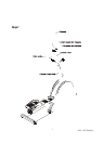
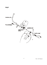
STEP 1: CONSOLE MAST ASSEMBLY
1. Locate the Console Mast and Console Mast Cover and slide the Cover onto the
Mast as far as it will go. Make sure the Console Mast Cover is facing the correct
way.
2. At the top opening of the Main Frame of the elliptical is a Computer Cable.
Unravel and straighten out the Computer Cable and feed it into the bottom of the
console mast tube and out of the top opening.
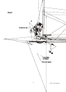
3. Install the Console Mast into the receiving bracket in the top of the Main Frame.
NOTE: there is one bolt already installed in the receiving bracket that will engage
with the slot at the bottom of the Console Mast. This needs to be tightened at the
end along with the three other console mast bolts.
4. Put the 1pc of 3/8" x 2T Split Washer onto the 1pc of 3/8" x 2-1/4" Hex Head
Screw and the 2pcs of 3/8 x 23 x 1.5T Curved Washers onto the 2pcs of 3/8" x
3/4" Hex Head Screws. Install, and hand tighten, the Hex Head Screw through
the left side of the receiving bracket into the Console Mast.
NOTE: There is a electrical wire running through the Console Mast Tube. Be
careful not to damage or pinch this Computer Cable during this procedure.
Damage to the Console could result. Install, and hand tighten, the 2pc of 3/8" x
3/4" Hex Head Screws through the front of the receiving bracket into the Console
Mast.
5. Using the 13/14m/m Wrench tighten the three bolts, and the fourth bolt which is
pre-installed, firmly. These bolts should be tightened as much as you possibly
can.
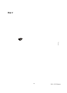
6. Locate the Console and the 4 pcs of M5 x 10m/m Phillips Head Screws.
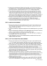
7. There will be three electrical wire connectors at the top opening of the console
mast, two 2 pin (hand pulse sensors), one 10 pin (main wire harness). Connect
these to the mating connectors on the back of the console. The connectors are
keyed so you cannot plug them in the wrong way so do not force them. The two,
2 pin connectors can be plugged into either connector on the back of the console.
8. Storing the excess wire back into the Console Mast, carefully install the Console
onto the mounting plate of Console Mast and secure using the 4 pcs of M5 x
10m/m Phillips Head Screws.
Assembly Instructions (E25)