


9
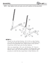
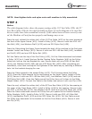
STEP 4
Notice:
The cable diagram below shows the proper routings of the 110”Lat Cable (#20), the 92”
Low Row Cable (#16) for the cable assembly in Steps 4 Use the diagram to be sure that
the two cables have been assembled correctly. If the cables have not been correctly rout-
ed, the Machine will not function properly and damage may occur.
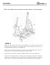
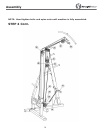
Draw the end, without the rubber ball, of the 110”Lat Cable (#20) to the open bracket at
the front of the Upper Frame (#19). Install a Pulley (#32). Secure it with one M10 ×45
Hex Bolt (#34), two Washers Dia10 (#39) and one M10 Nylon Nut (#38).
Draw the Cable along the Upper Frame towards the back of the machine to the first open
bracket. Install two Pulleys (#23). Secure it with one M10 ×80 Hex Bolt (#43), twoWash-
ers Dia10 (#39) and one M10 Nylon Nut (#38).
Pull the Cable over the top of the first Pulley (#23), Pull the Cable downward and attach
a Pulley (#32) to it. Install the two Double Floating Pulley Brackets (#46) to the Pulley.
Select any hole on the two Brackets for now. Secure them with one M10×45 Hex Bolt
(#34), two Washers Dia10 (#39) and one M10 Nylon Nut (#38). After completing the
installation, come back and adjust the tightness of the cable loop by selecting a different
hole. Let the brackets hanging for now.
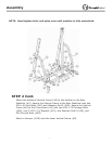
Draw the Cable upward to the second Pulley (#23). Thrill through above the Pulley
(#32). Draw the Cable towards to the last bracket on the Upper Frame. Install a Pulley
(#33). Secure it with one M10 ×80 Hex Bolt (#43), two Washers Dia10 (#39) and one
M10 Nylon Nut (#38). Draw the Cable around the Pulley then pull it down to the Slide
Weight Holder (#10). Connect the Cable to the Holder and secure it with one Clip (#30).
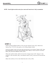
Draw the end, without the rubber ball, of the 92”Low Row Cable (#16) to the opening at
the upper of the Cross Brace (#04). Install a Pulley (#32) to the opening. Secure it with
one M10 x 45 Allen Bolt (#34), two Washers Dia10 (#39) and one M10 Nylon Nut (#38).
Draw the Cable underneath around the Pulley then pull upward to the Double Floating
Pulley Brackets (#46). Install a Pulley (#32). Secure it with one M10 ×45 Allen Bolt
(#34), twoWashers Dia10 (#39) and one M10 Nylon Nut (#38). Pull the Cable around
the Pulley then downward to the bracket on the the Cross Brace (#04). Secure it with
one Clip (#30).
NOTE: Hand tighten bolts and nylon nuts until machine is fully assembled.
Assembly