


11
www.keystness.com
Assembly
5
A2
P
N1
J1
N8
J1-1
A10
R
A3
For Cosmetic
Purposes Only
P1
N1
N3
(Not used in this model)
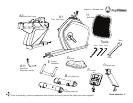
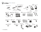
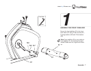
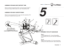
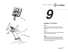
ASSEMBLY FOR SEAT SUPPORT FRAME
Attach the seat support tube (P1) to the seat slide assembly (A10)
and secure it using 4 allen screws (N1).
Note: Be careful not to pinch the sensor wire connection during assembly.
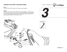
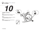
ASSEMBLY FOR LEFT HANDLEBAR
Step 1:
Connect pulse wire (J1-1) from left handlebar
(J1) and pulse wire (A3) from seat slide assembly
(A10).
Step 2:
Mount the left handlebar (J1) to the seat slide as-
sembly (A10) and secure with 4 allen screws (N8).
Use Tool
5mm
Use Tool
6mm
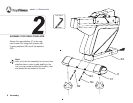
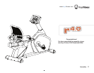
ASSEMBLY FOR BACK REST SUPPORT TUBE
Attach the back rest support tube (P) to the seat support tube (P)
and secure using 3 allen screws (N1) and 3 flat washers (N3).