


ASSEMBLY INSTRUCTION
Tools Required Assembling the Machine: Two Adjustable Wrenches and Allen
Wrenches. NOTE: It is strongly recommended this machine to be assembled by two
or more people to avoid possible injury.
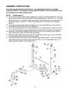
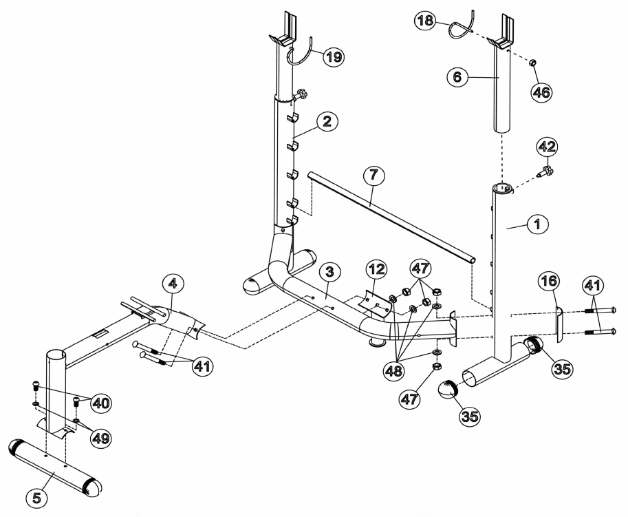
STEP 1 (See Diagram 1)
A.) Connect the Left and Right Upright Beams (#1) & (#2) by a Cross Brace (#3) in the mid-
span. Align the holes and secure them with one Bracket (#16), two M10 x 3 ¾” Carriage
Bolts (#41), two ∅ ¾” Washers (#48), and two M10 Aircraft Nuts (#47) on each end of
the Cross Brace. Plug four ∅ 3” Round End Caps (#35) to the base on the Upright
Beams.
B.) Place Backrest Adjustment Bar (#7) between the two Upright Beams on the selected
bar holder to obtain desired incline of Backrest.
C.) Insert two Crutches (#6) into the top openings on the Upright Beams. Secure them with
two Lock Knobs (#42) through selected holes to obtain desired height of the Supports.
D.) Insert the Left and Right Safety Hooks (#18) & (#19) into the holes on the Crutches
(#6). Secure them with two M8 Aircraft Nuts (#46).
E.) Attach the Main Seat Support (#4) to the Front Stabilizer (#5). Secure it with two M8 x
5/8” Allen Bolts (#40) and ∅ 5/8” Washers (#49).
F.) Connect the Main Seat Support (#4) and Rear Base Support (#12) to the Cross Brace
(#3). Align the holes and secure them with two M10 x 3 ¾” Carriage Bolts (#41), ∅ ¾”
Washers (#48) and M10 Aircraft Nuts (#47).
4