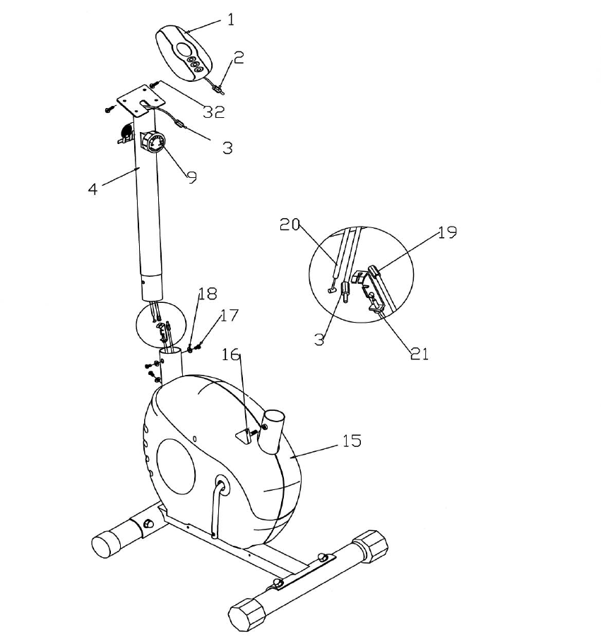
STEP 2 (See Diagram 2)
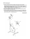
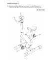
A.) Attach the Handlebar Post (#4) to the Main Frame (#15). Connect the Middle
Computer Sensor Wire (#3) from the bottom of Handlebar Post to the Lower Computer
Sensor Wire (#19) from the main body of the bike. Connect the Upper Tension
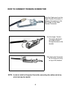
Connector (#20) to the Bracket on the Lower Tension Connector (#21). See HOW TO
CONNECT TENSION CONNECTOR on next page. Adjust exercise tension by using
the Tension Adjustment Knob (#9) on the Handlebar Post (#4).
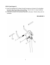
B.) Secure the Handlebar Post (#4) to the Main Frame (#15) with three M8 x 5/8” Allen
Bolts (#17) and Ø5/8” Bent Washers (#18).
C.) Connect the Middle Computer Sensor Wire (#3) from the top of the Handlebar Post
(#4) to the Upper Computer Sensor Wire (#2) from the Computer (#1). Hide the wires
inside the Post. Attach the Computer (#1) to the top of the Handlebar Post (#4) and
secure it with two M5 x ½” Philips Screws (#32).
DIAGRAM 2
5


