


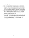
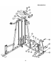
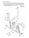
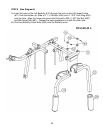
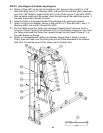
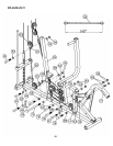
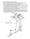
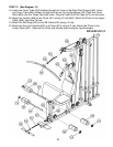
STEP 9 (See Diagram 9 & Cable Loop Diagram)
A.) Attach one end of the140” Leg Press Cable (#28) to the opening hole on the Left Seat
Support (#14), underneath the rubber bumper. Secure it with one M10 x 2 3/8” Allen
Bolt (#79), two ∅ ¾” Washers (#93), and one M10 Aircraft Nut (#90).
B.) Draw the Cable to the slotted opening on the Leg Press Frame (#17). Install a Pulley to
the opening then secure it with two ∅5/8” x ½” Pulley Bushings (#58), one M10 x 2 3/8”
Allen Bolt (#79), and one M10 Aircraft Nut (#90).
C.) Draw the Cable around the Pulley then toward the opening on the Left Seat Support
(#14). Repeat the Step B above to install a Pulley.
D.) Draw the Cable over the Pulley then downward to the open bracket on the Left Base
Frame (#3). Attach a Pulley to the Bracket then secure it with one M10 x 2” Allen Bolt
(#81), two ∅ ¾” Washers (#93), and one M10 Aircraft Nut (#90).
E.) Draw the Cable underneath the Pulley and towards the back of the machine, along the
Left Base Frame to the lower opening on the Left Vertical Beam (#4). Repeat Step B
above to install a Pulley. Draw the Cable around the Pulley then pull back towards the
lower opening on the Front Press Base (#15).
F.) Attach a Pulley to the opening. Secure it with one M10 x 8 ¼” Allen Bolt (#75), two ∅ ¾”
Washers (#93), and one M10 Aircraft Nut (#90).
G.) Draw the cable around the Pulley then pull the Cable towards the open bracket on the
Left Vertical Beam. Attach a U-shaped Bracket (#49) to the open Bracket. Install
another Pulley. Secure them with one M10 x 2” Allen Bolt (#81), two ∅ ¾” Washers
(#93), and one M10 Aircraft Nut (#90).
H.) Draw the Cable around the Pulley then back to the upper opening on the Front Press
Base (#15). Repeat Step F above to install another Pulley.
I.) Draw the Cable around the Pulley then towards the upper slotted opening on the Left
Vertical Beam (#4). Repeat Step B above to install a Pulley.
J.) Draw the Cable over the Pulley then downward to the open bracket on the Left Base
Frame. Install a Pulley. Secure the Pulley with an L-shaped Bracket (#48), one M10 x 2”
Allen Bolt (#81), two ∅ ¾” Washers (#93), and one M10 Aircraft Nut (#90).
K.) Draw the Cable underneath the Pulley then pull the Cable upward to the Single Floating
Pulley Bracket (#43) previously installed. Secure the Cable with one M10 x 1 3/8”” Allen
Bolt (#83), two ∅ ¾” Washers (#93), and one M10 Aircraft Nut (#90).
17