


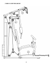
ASSEMBLY INSTRUCTION
Tools Required Assembling the Machine: Two Adjustable Wrenches, two Allen
Wrenches, and one Philips Screwdriver. NOTE: It is strongly recommended this
machine be assembled by two or more people to avoid possible injury.
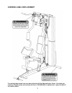
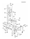
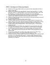
STEP 1 (See Diagram 1)
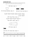
A.) Connect two Lower Guide Rods (#46) and two Upper Guide Rods (#45) with two M10
Stud Bolts (#48). Firmly thread the Rods together.
B.) Insert the two Lower Guide Rods (#46) into the holes on the Rear Base Frame (#2).
Secure them with two M10 x 1” Allen Bolts (#81) and Ø ¾” Washers (#86) from the
bottom. Slide two Ø 2 ½” x 1” Rubber Bumpers (#62) onto the Guide Rods.
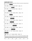
C.) Attach the Main Base Frame (#1) to the Rear Base Frame (#2). Secure it with two M10
x 2 ¾” Allen Bolts (#80), two Ø ¾” Washers (#86), and one 4” Curved Bracket (#22).
D.) Make sure the two triangular brackets on the Rear Base Frame are facing toward the
front.
E.) NOTE: Do not tighten all the Nuts and Bolts until instructed to do so.
F.) Attach the Front Base Frame (#3) to the Main Base Frame.
G.) Attach the Lower Vertical Frame (#4) onto the Main Base Frame and Front Base
Frame. Secure them together with two M10 x 2 3/8” Carriage Bolts (#83), one 5 ½”
Curved Bracket (#6), two Ø ¾” Washers (#86), and two M10 Aircraft Nuts (#90).
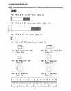
H.) Attach the Seat Support (#5) to the Lower Vertical Frame (#4). Secure it with two M10
x 2 3/8” Carriage Bolts (#83), one 5 ½” Curved Bracket (#6), two Ø ¾” Washers (#86),
and two M10 Aircraft Nuts (#90).
I.) Attach the Leg Developer (#7) to the Seat Support. Secure it with one M10 x 3 1/8”
Allen Bolt (#79), two Ø ¾” Washers (#86), and one M10 Aircraft Nut (#90). Do not over
tighten the Nut and Bolt. Make sure the Leg Developer is able to swivel.
J.) Attach the Upper Vertical Frame (#15) to the Lower Vertical Frame (#4). Secure them
with four M10 x 2 3/8” Carriage Bolts (#83), two 5 ½” 4-Holes Brackets (#16), four Ø ¾”
Washers (#86), and four M10 Aircraft Nuts (#90).
K.) Attach the Stopper Frame (#17) to the Upper Vertical Frame. Secure it with one M10 x
2 3/8” Allen Bolt (#78) and Ø ¾” Washer (#86).
L.) Attach a Swivel Pulley Bracket (#20) to the bracket behind the Upper Vertical Frame
(#15). Secure it with one M10 x 2 ½” Allen Bolt (#77), two Ø ¾” Washers (#86), and
one M10 Aircraft Nut (#90). Repeat to install the other side. Do not over tighten the
nuts and bolts. Make sure the Brackets are able to swivel.
7