


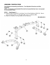
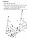
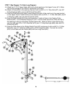
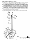
STEP 6 (See Diagram 6)
A.) Attach the Rear Vertical Frame (#9) onto the Rear Base (#8). Secure it with two M10
x 2 ½” Carriage Bolts (#74), Ø ¾” Washers (#69), and M10 Aircraft Nuts (#72).
B.) Attach the Rear Base (#8) and Front Vertical Frame (#10) to the Rear Stabilizer (#7).
Align the holes and secure them together with two M10 x 2 ½” Carriage Bolts (#74),
Ø ¾” Washers (#69), and M10 Aircraft Nuts (#72).
C.) Align the Front Vertical Frame (#10) to the Cross Brace (#6). Secure it with one 4
3/8” x 1 ¾” Bracket (#22), two M10 x 2 ½” Carriage Bolts (#74), two Ø ¾” Washers
(#69), and two M10 Aircraft Nuts (#72).
D.) Slide the Sliding Weight Post (#12) onto the Rear Vertical Frame (#9) from the top.
E.) Attach the Upper Frame (#11) onto the Front Vertical Frame (#10). Secure it with two
M10 x 5/8” Allen Bolts (#82) and Ø ¾” Washers (#69).
F.) Attach the rear of Upper Frame (#11) to the Rear Vertical Frame (#9). Secure it with
one M10 x 2 ½” Allen Bolt (#77), Ø ¾” Washer (#69), and 3 1/8” x 1 ¾” Bracket (#21)
to the upper hole. Secure the lower hole with one M10 X 2 ½” Carriage Bolt (#74), Ø
¾” Washer (#69), and M10 Aircraft Nut (#72).
G.) Securely tighten all Nuts and Bolts previously installed.
11