


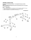
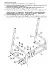
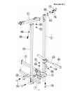
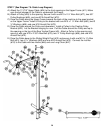

STEP 5 (See Diagram 5)
A.) Note: Do not tighten the Nuts and Bolts until instructed to do so.
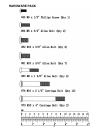
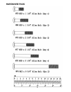
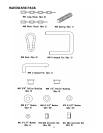
B.) Attach the top of Left Support (#2) to an Upright Beam (#1). Secure it with two M10 x 5/8”
Allen Bolts (#82) and Ø ¾” Washers (#69).
C.) Attach the Left Floor Stabilizer (#4) to the Upright Beam. Secure it with one M10 x 4”
Carriage Bolt (#73), ∅ ¾” Washer (#69), and M10 Aircraft Nut (#72).
D.) Attach the other end of the Left Floor Stabilizer (#4) and Rear Stabilizer (#7) to the bottom
of Left Support (#2). Align the holes and secure them together with one M10 x 2½”
Carriage Bolt (#74), Ø ¾” Washer (#69), and M10 Aircraft Nut (#72) to the upper hole.
Secure the lower hole with one M10 x 2 ½” Allen Bolt (#77) and Ø ¾” Washer (#69).
E.) Repeat procedure B, C, and D above to install the other side.
F.) Connect the Left & Right Supports (#2 & 3) with the Cross Brace (#6). Secure each end
with two M10x2½” Carriage Bolts (#74), ؾ” Washers (#69), and M10 Aircraft Nuts (#72).
10