


ASSEMBLY INSTRUCTION
Tools Required Assembling the Machine: Two Adjustable Wrenches and Allen
Wrenches.
NOTE: It is strongly recommended two or more people assembling this machine to
avoid possible injury.
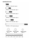
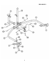
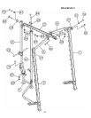
STEP 1 (See Diagram 1)
A.) NOTE: Do not tighten the Nuts and Bolts until instructed to do so.
B.) Attach one Diagonal Support (#3) to the Right Cross Brace (#15). Secure it with one 3
¾” x 2 3/8” Bent Bracket (#26), M10 x 2 3/8” Carriage Bolt (#81), Ø ¾” Washer (#87),
and M10 Aircraft Nut (#89) to the front hole. Secure the back hole with one M10 x 2
1/8” Allen Bolt (#74) and Ø ¾” Washer (#87). Repeat the same procedure to install the
other Diagonal Support to the Left Cross Brace (#14).
C.) Attach the Left & Right Cross Brace (#14 & #15) to the Rear Vertical Beam (#10).
Secure them together with two M10 x 2 ¾” Carriage Bolts (#83), Ø ¾” Washers (#87),
and M10 Aircraft Nuts (#89).
D.) Attach the Foot Plate (#34) to the front of Rear Vertical Beam (#10). Attach the Weight
Glide Post Base (#11) to the back of Rear Vertical Beam. Align the holes and secure
them together with two M10 x 2 3/8” Allen Bolts (#75), four Ø ¾” Washers (#87), and
two M10 Aircraft Nuts (#89).
E.) Secure the Foot Plate (#34) to the Rear Vertical Beam (#10) with one M10 x 3” Allen
Bolt (#77), two Ø ¾” Washers (#87), and one M10 Aircraft Nut (#89).
8