


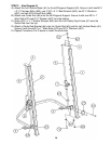
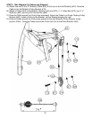
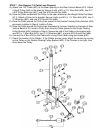
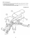

STEP 7 (See Diagram 7 & Cable Loop Diagram)
A.) Attach one 123” Cable (#37) to the lower opening on the Rear Vertical Beam (#10). Attach
a Small Pulley (#45) to the opening. Secure it with a M10 x 2 ¾” Allen Bolt (#76), two Ø 1”
x 5/8” Pulley Bushings (#41), and one M10 Aircraft Nut (#89).
B.) Draw the Cable underneath the Pulley to the open bracket on the Weight Glide Post Base
(#11). Attach a Pulley to the bracket. Secure it with one M10 x 1 ¾” Allen Bolt (#73), two ∅
¾” Washers (#87), and one M10 Aircraft Nut (#89).
C.) Draw the Cable around the Pulley then upward to the Double Floating Pulley Bracket (#23)
previously installed in Step-5. Install a Pulley.
D.) Draw the Cable around the Pulley then downward to the open bracket on the back of Rear
Vertical Beam (#10). Install a Pulley then draw the Cable upward to the Single Floating
Pulley Bracket (#24) installed in Step-6. Secure the end of the Cable to the bracket with
one M10 x 1” Allen Bolt (#72), two ∅ ¾” Washers (#87), and one M10 Aircraft Nut (#89).
E.) Connect the V Bar (#35) to the Cable with a Long Chain (#46) using two Hooks (#48).
F.) Check the tension of the Cables. If the Cables are too loose, adjust the tension by moving
up the Pulley on the Double Floating Pulley Bracket (#23). If the Tension is too tight, then
move down the Pulley.
18