


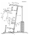
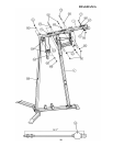
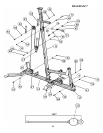
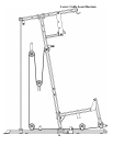
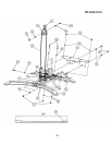
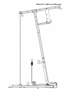
STEP 7 (See Diagram 7 & Lower Cable Loop Diagram)
A.) Attach the 164” Lower Cable (#35) to the opening on the Leg Developer (#8). Attach a
Pulley (#47) to the opening. Secure it with one M10 x 2 ½” Allen Bolt (#84), two ∅
7/8” Leg Developer Pulley Bushings (#52), and one M10 Aircraft Nut (#91).
B.) Draw the Cable underneath the Pulley to the open bracket on the Front Base Frame
(#12). Attach a Pulley to the bracket. Secure it with one M10 x 1 ¾” Allen Bolt (#83),
two ∅ ¾” Washers (#92), and one M10 Aircraft Nut (#91).
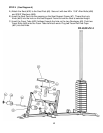
C.) Draw the Cable underneath the Pulley towards the back of the machine through the
bottom opening on the Vertical Frame (#4) to the open bracket on the Rear Base
Frame (#14). Repeat Procedure B above to install a Pulley.
D.) Draw the Cable underneath the Pulley then pull upward to the Double Floating Pulley
Bracket (#22) previously installed in STEP-6. Repeat Procedure B above to install a
Pulley. After completing the entire cable system, come back to the Double Floating
Pulley Bracket and adjust the height of the lower Pulley to adjust the tightness of the
Cables. Move up the hole to increase the tension. Move down the hole to loose the
tension.
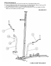
E.) Draw the Cable around the Pulley then downward. Attach the Cable to an Angled
Double Floating Pulley Bracket (#27). Repeat Procedure B above to install a Pulley.
Let the Bracket hanging for now.
F.) Draw the Cable around the Pulley then upward to the opening on the Vertical Frame
(#4). Attach a Pulley to the opening. Secure it with one M10 x 3 ½” Allen Bolt (#77),
two Pulley Bushings (#49), and one M10 Aircraft Nut (#91).
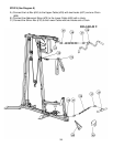
G.) Insert the Cable through a Ball Stopper (#76). Attach the Cable to a U-shape Cable
Connector (#41). Attach a Hook (#37) to the Connector. Secure the Connector and
Hook with one M10 x 1 3/8” Allen Bolt (#85), two ∅ ¾” Washers (#92), and one M10
Aircraft Nut (#91).
18