


8
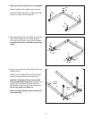
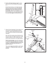
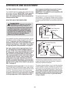
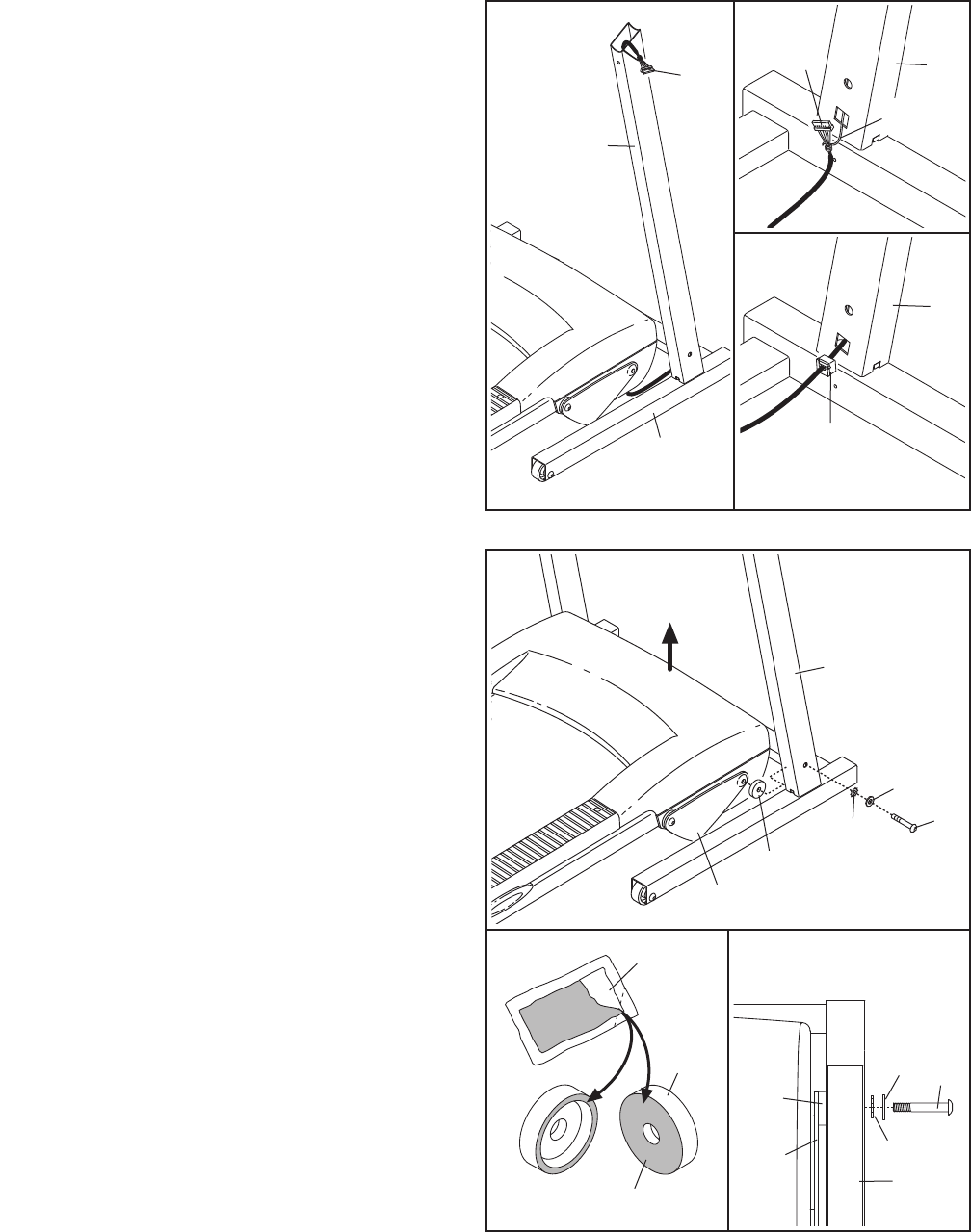
4. Position the Base (52) as close to the front of the
treadmill as possible, as shown.
S
ee the upper inset drawing. Locate the wire
tie in the lower end of the Right Upright (54). Tie
t
he wire tie securely around the end of the Wire
Harness (39). Then, locate the other end of the
wire tie in the upper end of the Right Upright.
Pull the upper end of the wire tie until the Wire
Harness extends from the upper end of the Right
Upright. Secure the Wire Harness to the Right
Upright so that it will not fall inside.
See the lower inset drawing. Press the indi-
cated Grommet (49) into the Right Upright (54).
5
4
54
49
39
Wire Tie
52
4
39
54
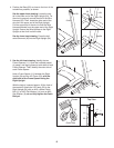
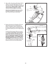
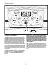
5. See the left inset drawing. Identify the two
Frame Spacers (11). Open the included packet
of grease, and apply grease to both sides of both
Frame Spacers. Then, identify the outer side of
each Frame Spacer.
Hold a Frame Spacer (11) between the Right
Upright (54) and the Lift Frame (23), with the
outer side of the Frame Spacer facing the
Right Upright.
With the help of a second person, lift the front of
the treadmill. Attach the Lift Frame (23) to the
Right Upright (54) with an M10 x 60mm Patch
Bolt (1), an M10 Flat Washer (14), and an M10
Star Washer (9); do not fully tighten the Patch
Bolt yet.
5
54
1
1
11
23
14
54
14
9
23
11
9
11
Grease
Outer Side
Top View