


12
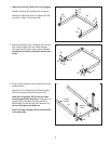
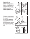
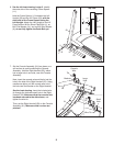
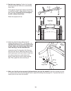
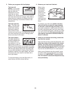
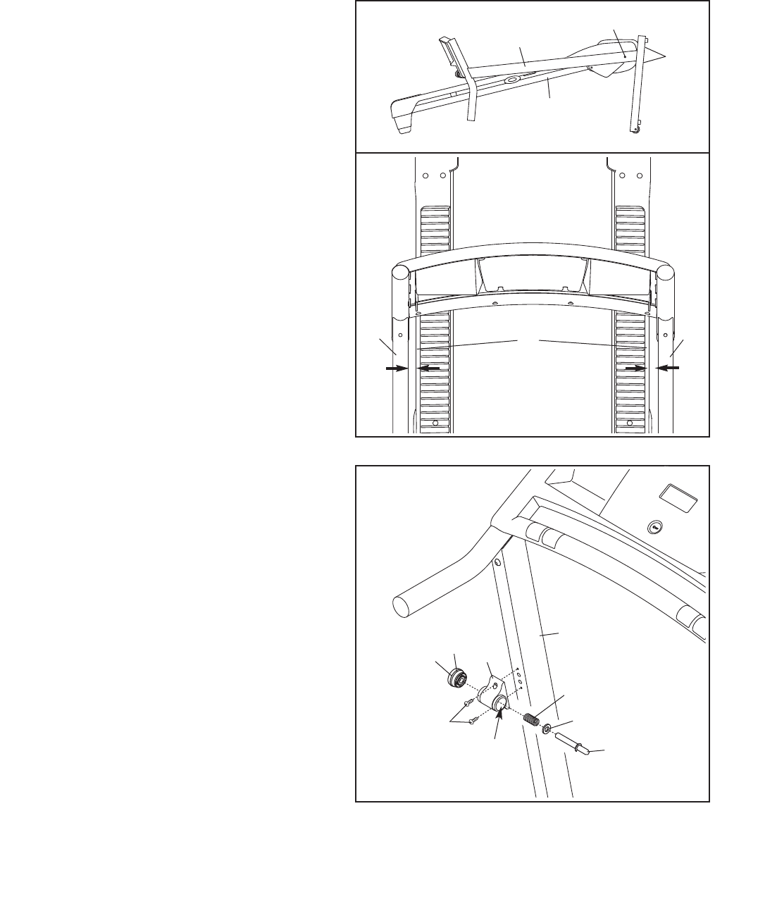
12. See the lower drawing. Position the Uprights
(53, 54) so that the Frame (51) is centered be-
tween them.
Firmly tighten the two M10 x 60mm Patch Bolts
(
1) and the four M10 x 58mm Bolts (2) (only one
side is shown). Be careful not to overtighten
the M10 x 60mm Patch Bolts.
Raise the Uprights (53, 54).
12
2
53, 54
1
53
51
54
Top View
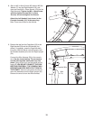
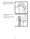
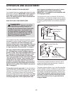
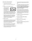
13. Attach the Latch Housing (48) to the Left
Upright (53) with two #10 x 1" Tek Screws (13);
start both Tek Screws, and then tighten each
of them. Make sure that the large hole in the
Latch Housing is on the indicated side.
Locate the Latch Pin Assembly (24). Remove
the knob from the pin. Make sure that the collar
and the spring are on the pin. (Note: If there are
two collars, place one on each side of the
spring.) Insert the pin into the Latch Housing
(48). Then, tighten the knob onto the pin.
13
Pin
Spring
Collar
48
53
Large Hole
13
24
Knob
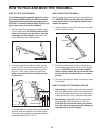
14. Make sure that all parts are properly tightened before you use the treadmill. Keep the included hex keys
in a secure place. One of the hex keys is used to adjust the walking belt (see page 21). To protect the floor or
carpet, place a mat under the treadmill.
5
1