


10
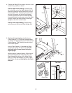
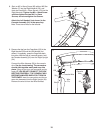
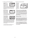
8. Start an M5 x 16mm Screw (85) with an M5 Star
W
asher (7) into the Right Handrail (33), and
then start two M4.2 x 19mm Screws (10) into the
Right Handrail. Tighten the M5 x 16mm Screw
and then tighten the two M4.2 x 19mm
S
crews; do not overtighten the Screws.
Attach the Left Handrail (not shown) to the
Console Assembly (91) in the same way.
Note: There are no wires on the left side.
8
33
85
7
1
0
91
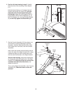
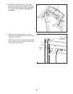
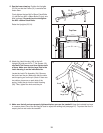
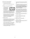
9. Remove the ties from the Cage Nuts (103) in the
Right Handrail (33) and the Left Handrail (not
shown). If necessary, press the Cage Nuts back
into place. With the help of a second person, hold
the Console Assembly (91) near the Right Upright
(54).
Connect the Wire Harness (39) to the console
wire. See the inset drawing. The connectors
should slide together easily and snap into
place. If they do not, turn one connector and try
again. IF YOU DO NOT CONNECT THE CON-
NECTORS PROPERLY, THE CONSOLE MAY
BECOME DAMAGED WHEN YOU TURN ON
THE POWER. Insert the connectors and the ex-
cess wire downward into the Right Upright (54).
Remove the wire tie from the Wire Harness.
9
91
54
39
Console Wire
39
33
Wire
Tie
103
Console
Wire