


11
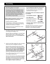
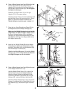
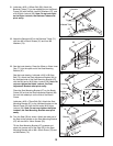
17. Press a 51mm x 76mm Outer Cap (56) onto each
end of the Stabilizer (58).
Attach the Stabilizer (58) to the Bench Frame (52)
with two M10 x 58mm Carriage Bolts (57) and two
M10 Nylon Locknuts (29). Attach the Stabilizer so
that the warning decal is in the position shown.
Note: Do not tighten the Nylon Locknuts yet.
17
57
56
29
52
Decal
58
56
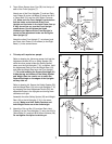
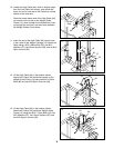
18. Press a 50mm Square Outer Cap (65) onto each end
of the Bench Base (53).
Attach the Bench Base Joint Plate (64) to the Bench
Base (53) with two M10 x 68.5mm Bolts (75), two
M10 Washers (37), and two M10 Nylon Locknuts
(29).
Attach the Bench Leg (48) to the Bench Base Joint
Plate (64) with two M10 x 68.5mm Bolt (75), two M10
Washers (37), and two M10 Nylon Locknuts (29). Be
sure the welded nut is in the position shown.
Note: Do not tighten the Nylon Locknuts yet.
18
75
37
37
75
37
37
48
29
64
65
65
53
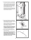
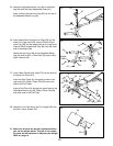
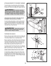
19. Attach the Bench Leg (48) to the Bench Frame (52)
with two Bench Joint Plates (63), four M10 x 72mm
Bolts (34), and four M10 Nylon Locknuts (29).
Note: Tighten all the M10 Nylon Locknuts (29)
used in steps 17-19.
19
48
29
63
52
34
63
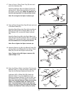
20. Press two 25mm x 38mm Inner Caps (72) into each
Backrest Tube (71). Press two 25mm x 38mm Inner
Caps into the Backrest Adjustment Bracket (79).
Lubricate a M10 x 192mm Bolt (66). Attach the
Backrest Tubes (71) to the welded tube on the
Backrest Adjustment Bracket (79) with the Bolt, two
M10 Washers (37) and a M10 Nylon Locknut (29).
Make sure that the Backrest Tubes are turned as
shown. The indicated holes are closer to one
side. Turn the Backrest Tubes so the holes are
closer to the floor. Do not over tighten the Nylon
Locknut; the Backrest Tubes must pivot easily.
20
72
29
37
37
79
Lubricate
Holes
Welded
Tube
72
72
66
71
Welded Nut