


ENGLISH INSTRUCTIONS
IMPORTANT! WRITE MODEL NUMBER FROM BOX ONTO
PAGE 1 OF THIS OWNERS MANUAL
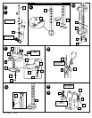
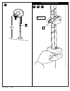
1.
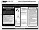
Mark middle and bottom pole sections indicated distance with tape.
2. Make sure ground is level with playing surface, then dig pole hole.
WARNING: CONTACT UTILITIES BEFORE DIGGING.
NOTE: Maximum distance from edge of hole to edge of playing surface
6” (15.2 cm).
WARNING: THIS HOLE SIZE REPRESENTS THE MINIMUM REQUIREMENT
FOR IDEAL CONDITIONS. THE LOCATION (HILL/INCLINE) OF THE POLE,
SOIL CONDITIONS (SAND/CLAY) AND OTHER FACTORS COULD REQUIRE A
LARGER HOLE SIZE AND CONCRETE FOOTING.
3. Insert and secure bottom pole section (3) into ground sleeve (4).
4. Fill hole approximately 1/3 full with concrete. Insert ground sleeve assembly and
center in hole. Fill hole completely with concrete.
NOTE: Make sure that bottom of ground sleeve flange is level with playing
surface.
5. Tamp down concrete to release air pockets and build drainage hill. Level pole
section in all directions several times while concrete is curing.
NOTE A: Mark here for tape.
NOTE B: Keep flange pushed down to concrete and leveled.
IMPORTANT! Wait minimum of 24 hours before going on to next step.
Concrete must cure.
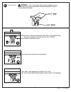
6. After concrete has cured, remove bottom pole section from ground sleeve (4).
Place anti-skid tape (6) around bottom of pole.
NOTE A: Place top edge of tape on mark.
NOTE B: Tape prevents the pole from rotating during play.
7. Install ground sleeve cap (5) onto bottom pole section. Stack and bounce bottom
and middle pole sections together. Bounce pole sections together until middle
section no longer moves toward taped reference mark.
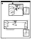
8. Stack upper pole section (1) to bottom pole assembly and continue bouncing until
poles no longer move toward taped reference marks.
IMPORTANT! Pole sections should have a 3-3/4” (9.5 CM) minimum overlap.
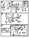
9. Snap tinnerman nut (7) onto inner channel (8). Place inner channel into outer
channel (9) as shown.
10. Slide handle (10) into position as shown and secure with bolts (11), washers (12),
and nuts (13). Tighten completely.
11. Install bolt (14), washers (12), and nut (15) as shown.
NOTE: Tighten until washers (12) are no longer loose. Assemble trigger (16) to
handle assembly as shown and secure with bolt (17) and washer (12). Tighten
completely.
12. Install trigger return spring (18) to handle assembly (8, 9) as shown.
WARNING: USE EYE PROTECTION WHEN INSTALLING SPRINGS.
13. Attach logo labels (19) to inner channel (8).
14. Attach spring (22) to pins (21) and install pins (21) onto pole mount bracket (23).
15. Attach other spring (22) to opposite side. NOTE: Gently enlarge eyelets of spring
with pliers if springs do not fit over pins.
WARNING: USE EYE PROTECTION WHEN INSTALLING SPRINGS.
16. Install pole mount assembly with carriage bolts (24), reinforcement bracket (31) as
shown. Tighten flange nuts (13) completely.
17. Push back sliding pin (21) as shown in Figure A to fit adjustable system assembly
through pole mount assembly. Then attach spring covers (25, 26) onto pole mount
bracket (23) with bolt (27), and nut (13) as shown in Figure B.
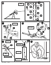
18. Install spacers (28) and springs (38) onto backboard brackets (29) with
bolts (30, 43), washers (47) and lock-nuts (15, 32) as shown.
IMPORTANT! It is necessary for all parts to be installed for this mechanism
to work safely and properly.
19. Assemble elevator tubes (33, 34) as shown. Tighten completely. Bend bracket (29)
to line up with holes in backboard.
IMPORTANT! Test fit bolts into holes of brackets (29) and carefully rock
them in a circular motion to ream out paint from holes if necessary.
20. Support pole on sawhorse. Attach backboard assembly to top pole section (1).
NOTE: Two people are recommended for this step, use caution, elevator
assembly is heavy.
21. Install handle assembly to lower elevator tubes (34) using bolt (35), spacers (37),
and nut (36) as shown. NOTE: Before going on to next step, adjust adjustable
system assembly to the 10’ setting.
22. Insert bolt (35) through left side upper elevator tube (33), then stretch spring (38)
onto bolt (35). Insert bolt (35) through right side upper elevator tube (33) and
secure with nut (36).
WARNING: USE EYE PROTECTION WHEN INSTALLING SPRINGS.
23. Place re-bar (36” section - not included) into bottom pole section (3) as shown.
Secure pole end with tape (not included) to retain re-bar inside the bottom pole
section (3).
NOTE: Make sure that concrete does not bulge from the end of pole assembly.
Fill pole with concrete approximately 1” (2.54 cm) below bottom hole as shown.
Allow concrete to completely cure.
IMPORTANT! Failure to fill your pole completely with concrete as described
in these instructions will void all warranties written and implied.
IMPORTANT! Wait minimum of 24 hours before going on to next step.
Concrete must cure.
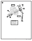
24. Remove tape, install pole cap (45), fit pole assembly into sleeve (4).
IMPORTANT! Position pole section so the elevator assembly is
perpendicular with playing surface.
WARNING: TWO PEOPLE ARE RECOMMENDED FOR THIS STEP. POLE
FILLED WITH CONCRETE WEIGHS APPROXIMATELY 125 LBS. (56.7 KG).
USE PROPER PRECAUTION.
IMPORTANT! The elevator holes MUST be parallel with playing surface.
25. Use wedge to tap cap of ground sleeve until tight.
26. Install rim (40) to backboard as shown. NOTE: Mounting nuts and bolts supplied
with rim hardware.
WARNING: TWO PEOPLE ARE NECESSARY TO MOUNT BACKBOARD
ASSEMBLY TO THE POLE. ONE PERSON SHOULD NOT ATTEMPT TO DO
THIS ALONE.
WARNING: MOUNTING THE BACKBOARD ASSEMBLY TO THE POLE IS
PERFORMED AT AN ELEVATED HEIGHT. USE PROPER PRECAUTION.
27. Apply height adjustment label (45) to front of pole as shown.
28. Grasp handle and depress lever.
WARNING: DO NOT ALLOW CHILDREN TO ADJUST HEIGHT.
29. Push toward pole while holding lever. Raise or lower lever to desired height while
pushing forward on handle.
30. Release handle making sure that horizontal pin (21) is locked into slot.
WARNING: USE OF THIS PRODUCT WITHOUT PROPER INSTALLATION OF
SMART CLIPS, OR WHEN ALL SMART CLIPS ARE NOT PRESENT COULD
RESULT IN BODILY HARM. BE SURE TO FOLLOW DIRECTIONS
CAREFULLY.
31. Install net clips as shown. (See illustration)
32. Install net as shown. (See illustration)
2
P/N 214969 08/02