


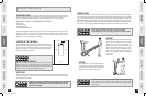
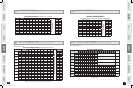
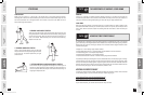
A With running deck in lowered
position, place
CONSOLE on
upright masts. Slide the brackets
that are underneath the console
into the top holes of the upright
masts.
B Place LOCK WASHER (E) and BOLT
(D) into flat side of LEFT upright
MAST and tighten.
C Place ARC WASHER (F) and BOLT
(D) into curved side of LEFT
upright MAST and tighten.
* Be sure to tighten bolts after all are
lined up.
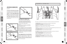
A Gently lift RIGHT side of the
console to connect the
CONSOLE
CABLE. Carefully tuck wires in
mast to avoid damage.
NOTE: Do
not pinch console cable or grip
pulse wires.
B Repeat steps 2-3 above to
assemble the right side upright
mast and console.
INTRODUCTION
IMPORTANT
PRECAUTIONS
ASSEMBLY
BEFORE
YOU BEGIN
TREADMILL
OPERATION
CONDITIONING
GUIDELINES
TROUBLESHOOTING
& MAINTENANCE
LIMITED
WARRANTY
9
A S S E M B LY S T E P 3
A S S E M B LY S T E P 4
INTRODUCTION
IMPORTANT
PRECAUTIONS
ASSEMBLY
BEFORE
YOU BEGIN
TREADMILL
OPERATION
LIMITED
WARRANTY
8
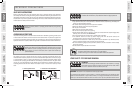
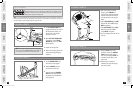
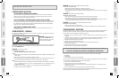
DO NOT CUT STRAPS UNTIL STEP 1.4!* Disassemble box and remove the
cardboard packaging that is not beneath the treadmill. Do not attempt to lift the
treadmill at this time. Reach under treadmill running deck to locate parts box.
Remove plastic wrap from console masts.
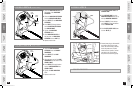
NOTE: It is recommended that you apply grease to the threads of each bolt as you assemble your treadmill, to
prevent loosening and noise. Also, during each assembly step, ensure that ALL nuts and bolts are in place and
partially threaded in before completely tightening any ONE bolt.
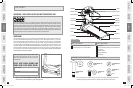
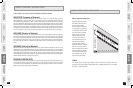
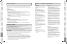
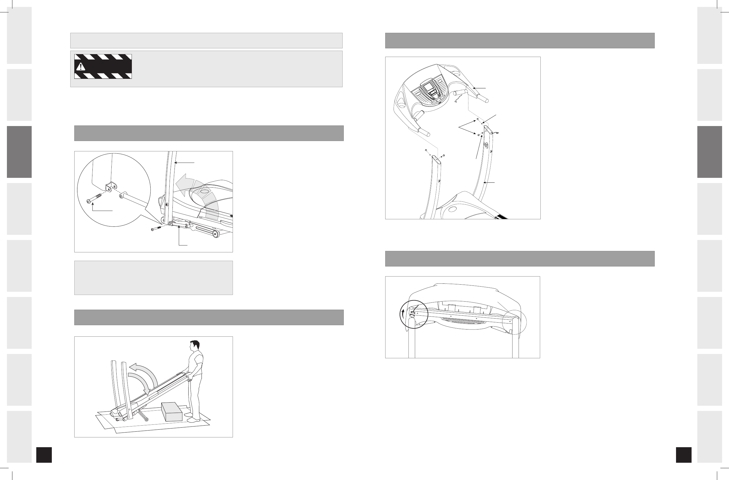
Lift LEFT CONSOLE MAST into
upright position. Be sure to hold
the console mast firmly, as it
will not stay in the upright
position on it’s own.
Move LEFT SIDE LINKAGE ARM
into position. Insert
TEFLON
WASHER (B) (2 pcs) and BOLT
(A) and tighten.
Repeat on the right side.
Now cut the banding straps and
remove remaining packaging
material.*
Lift the RUNNING DECK until
lock latch is fully engaged.
Remove CONSOLE from box
and place out of the way.
Lower the treadmill RUNNING
DECK from the folded position
by stepping on LOCK LATCH on
lower right side.
A S S E M B LY S T E P 1
A S S E M B LY S T E P 2
A
B
C
D
A
B
C
P R E - A S S E M B LY
TROUBLESHOOTING
& MAINTENANCE
CONDITIONING
GUIDELINES
* NOTE: If the straps have been removed before completing
STEP 1, refer to the TROUBLESHOOTING section (page 26)
in order to restore the treadmill to its proper position.
LEFT CONSOLE MAST
LEFT SIDE LINKAGE ARM
BOLT A
1
3
2
ASSEMBLED IN STEP 3
WARNING
CST3.5-4.5 Treadmill Rev0.2.indd 8-9 4/21/05 11:22:36 AM