


ASSEMBLY
INSTRUCTIONS
FITNESS SYSTEMS
R
HOIST
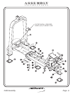
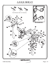
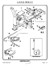
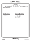
1 - Seat Assembly
21 - ROM/CAM Assembly
46 - Clamp
47 - Pulley Bracket
48 - Cam Belt 37”x 15/16”x 1/8”
50 - U-Bracket
Part Descriptions
M - 3/8”-16 x 3/4” Button Head Screw
N - 1/4”-20 x 1 1/4” Socket Head Screw
J - 3/8”-16 x 2 3/4” Button Head Screw
AD - 1/4” Flat Washer
AE - 3/8” Flat Washer
AF - 3/8” Lock Washer
BA - 1/4” Lock Nut
CM - 3 1/4” Pulley
CN - 3 1/4” Pulley
(White Zinc)
(Black Zinc)
(White Zinc)
(Black Zinc)
(White Zinc)
(White Zinc)
(White Zinc)
(Non-Threaded)
Hardware Descriptions
2406 Assembly
Page 13
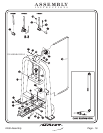
FRAME ASSEMBLY
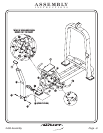
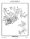
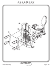
Step 2e
In this step, attach (CN) and the (50) to the (1). Now assemble (CM)
and (47). Next you will need to secure (48) to (21) by sandwiching
between two (46’s),insure smooth side of (48) is facing (21). Now secure
the other end of (48) to the rear of (47) in similar fashion. Then
bolts including all previously hand tightened bolts
Wrench
tighten .