


1910
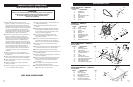
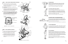
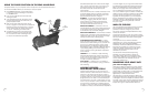
STEP 9 – Computer Installation
a) Remove battery door from back of
Computer, insert (4) “C” batteries
and replace the battery door.
Note: DO NOT use rechargeable
batteries, doing so will cause a
short and destroy the computer.
b) Remove (4) Phillips Bolts from back
of Computer.
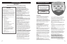
c) Connect Computer Wires and
Handlebar Tube Wires together and carefully tuck
wires into Handlebar Tube, see Figure 9c.
d) Mount Computer to Handlebar Tube using the
(4) Phillips Bolts removed in Step 9b and tighten.
e) Book Holder can be attached to the front of the
Computer at any time.
4
1
3
2
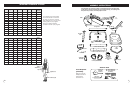
four "C" batteries
back of
computer
handlebar
tube
battery
door
Back
View
9b
9a
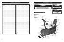
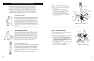
STEP 8 – Front Handlebar
Installation
a) Remove (2) Allen Bolts, (2) Washers and
(2) Nylon Nuts from Front Handlebar.
b) Align bolt holes in Front Handlebar with
holes in Handlebar Tube, see Figure 8.
c) Re-install (2) Allen Bolts, (2) Washers and
(2) Nylon Nuts that were removed in step
8a and tighten.
M8 nylon nuts
M8 washers
front handlebar
M8 x 60mm
allen bolts
handlebar tube
Figure 8 - Install Front Handlebar
Figure 9 - Install Computer
book holder
connectors
handlebar
tube
computer
Front
View
9c
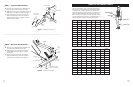
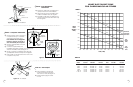
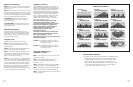
TABLE 2
Exercise Warm Up THR% Cool Down Total Sessions Total Time
Week Period Minutes Period Time Per Wk. Per Wk.
&1 & 2 5 min 60-65% -8 5 min 17 min 3 51 min
&3 & 4 5 min 65-70% -10 5 min 20 min 3 60 min
&5 & 6 5 min 70-75% -15 5 min 25 min 3 75 min
&7 & 8 5 min 70-80% -20 5 min 30 min 3 90 min
& 9 & 10 5 min 70-85% -25 5 min 35 min 3 105 min
&11 & 12 5 min 70-85% -25 5 min 35 min 3 105 min
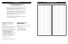
HEART RATE TARGET ZONE
FOR CARDIOVASCULAR FITNESS
TABLE 1
Maximum
Attainable
Heart Rate
85%
Target
Zone
70%
Target
Zone
Heart
Rate
(Beats/
Min)
20 25 30 35 40 45 50 55 60 65 70 75 80
200
190
180
170
160
150
140
130
120
110
100
195
165
136
190
161
133
185
157
129
180
153
129
175
148
129
170
144
119
165
140
115
160
136
112
155
131
108
150
127
105
145
123
101
140
119
98
AGE (YRS)
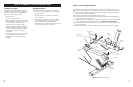
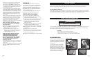
STEP 10 – AC Adapter
a) Plug Adapter into receptacle
locate in the Main Frame near
the Front Foot Tube, see Figure 10.
b) Insert Adapter plug into outlet
in wall.
Figure 10 - AC Adapter
main
frame
front foot
tube