


9
5) With the sensor in the upper liquid, increase the gain, using the switch if necessary, until the
control unit changes to ‘Normal’. Note the position of the potentiometer. If the control unit does
not change to normal then the end of the scale should be used as a reference.
6) The gain should be set half way between the settings found in steps 3 and 5.
7) Check that the unit switches correctly giving a normal indication in the lower liquid and an alarm
indication in the upper liquid.
8) If an inverse acting head amplifier is used, ‘Normal’ and ‘Alarm’ conditions quoted above are
reversed.
iv) Interface Sensors – Reflection Method
1) Check that the sensor is clean and that the control unit delay is fully anti-clockwise.
2) Immerse the sensor in each liquid in turn, adjusting the gain potentiometer until the control unit
changes from ‘Alarm’ to ‘Normal’. Note the position at which this occurs for both liquids. If the
two positions differ by more than two divisions, the attenuation method can be used.
3) For the reflection method, the gain should be set one division greater than the higher of the two
settings found in step 2.
4) This gives a rough calibration. The gain should be increased if spurious alarms cannot be
overcome by increasing the delay. The gain should be decreased if the unit fails to detect
interfaces.
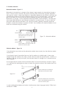
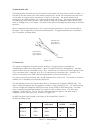
5) For the reflection method the sensor should be mounted at an angle of 10º to the horizontal.
6) Where the interface consists of an emulsion layer, the sensor functions as the reflection method,
giving an ‘Alarm’ condition only at the interface, but in this case, it is not necessary to angle the
sensor at 10º.
7) If an inverse acting head amplifier is used, ‘Normal’ and ‘Alarm’ conditions quoted above are
reversed.
v) Sludge Sensor
1) Ensure that the control unit delay is set fully anti-clockwise.
2) When used with a 433S type sensor, the sensor should be positioned at the top of the sludge
blanket during calibration.
3) The gain can now be adjusted until the control unit changes state with the sensor in this position.
4) Check that raising and lowering the sensor into and out of the sludge blanket causes the control
unit to switch.
5) If the pipe section is used, the tank should be de-sludged until the pipe contains solids at roughly
the required switching point. The gain is then adjusted until the unit just switches. This should
only be done when the slurry in the pipe is flowing.
6) The pipe section should be installed with the sensors in a horizontal plane, and with 10 diameters
of straight unrestricted pipe upstream and six diameters downstream.