


8
Calibration procedure by sensor type
i) Hi-Sens Sensors
1) Ensure that the sensor is clean and dry, that nothing is touching the sensor body, and that the
delay adjustment on the control unit is fully anti-clockwise.
2) Set the gain potentiometer in the head amplifier fully anti-clockwise, and the gain switch (if
fitted) in the low gain position.
3) The control unit should now indicate ‘alarm’ (or ‘normal’ for inverse acting head amplifiers).
4) Gradually increase the gain until the control unit indicates ‘normal’ (or ‘alarm’ for inverse acting
control units). This is beginning of the operating band.
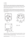
5) The optimum gain setting can be found by rotating the potentiometer a further 30º (one division on
the clock face),
6) Check that the control unit switches satisfactorily when the sensor is immersed in the liquid.
ii) Gap Sensors
1) Ensure that the sensor is clean, and immerse it in a sample of the liquid, making sure that the gap
is full of the liquid, and unobstructed. Adjust the time delay on the control unit fully anti-
clockwise.
2) Set the head amplifier gain control fully anti-clockwise, with the gain switch (if fitted) in the high
gain position.
3) The control unit should now indicate alarm (or normal for inverse acting head amplifiers) if it does
not switch to low gain (if a gain switch is fitted).
4) Gradually increase the gain until the control unit indicates normal (or alarm for inverse acting
head amplifiers). Note the position of the potentiometer and gain switch. This is the lower end of
the working range.
5) Remove the sensor from the liquid, and allow the liquid to drain away. Ensure that nothing is
touching the sensor body. The control unit should now indicate alarm (or normal for inverse
acting head amplifiers).
6) Gradually increase the gain until the control unit indicates normal (or alarm for inverse acting
head amplifiers). Note the position of the potentiometer and gain switch. This is the upper limit
of the working range.
7) The optimum gain setting is midway between the points recorded in steps 4 and 6. It may be
necessary to estimate this point if the gain switch has been used.
8) Check that the control unit switches correctly when the sensor is immersed in the liquid.
iii) Interface Sensors – Attenuation Method
1) Ensure that the sensor is clean, and that the delay on the control unit is fully anti-clockwise.
2) With the sensor in the lower liquid adjust the gain potentiometer anti-clockwise, using the gain
switch if necessary, until the control unit changes from ‘Normal’ to ‘Alarm’.
3) Note the position of the potentiometer. If the control unit does not switch to ‘Alarm’ use the
bottom end of the scale as a reference.
4) Immerse the sensor in the upper liquid. The control unit should now indicate ‘Alarm’. If it does
not then the reflection method should be used.