


6 7
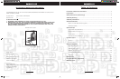
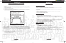
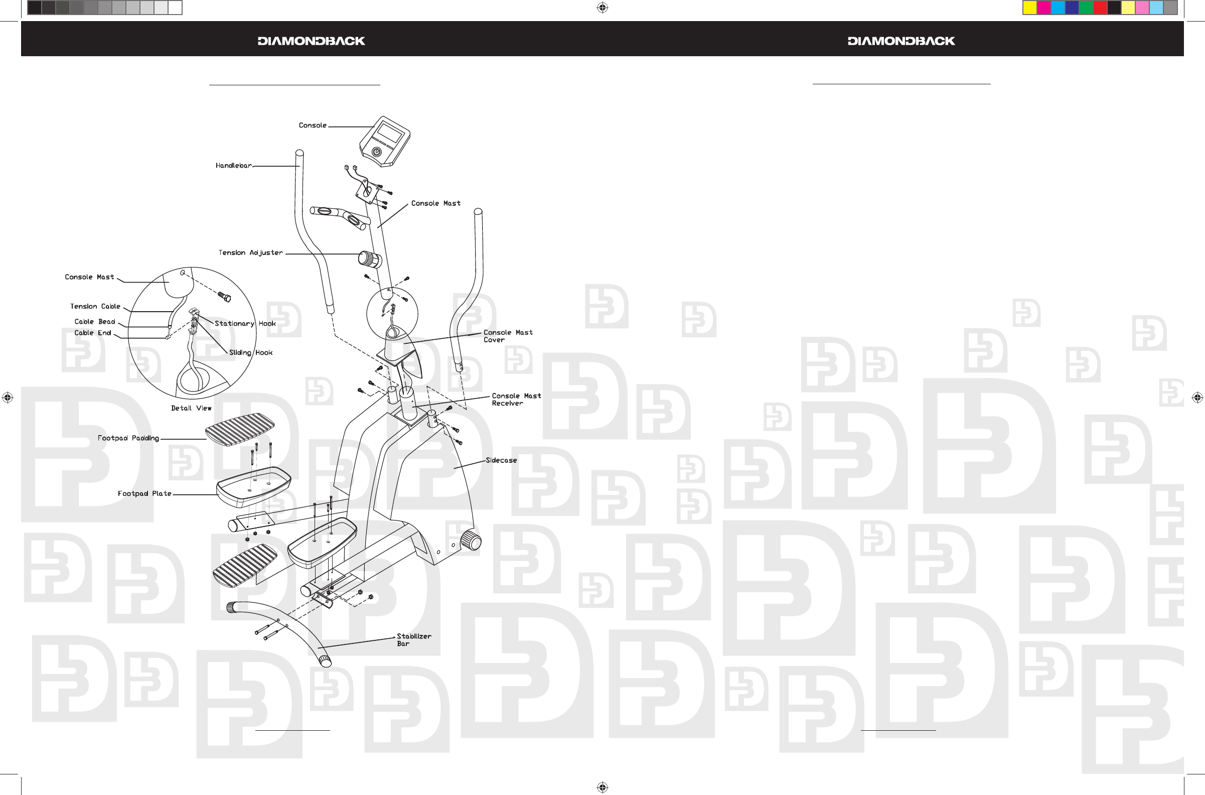
Assembly Drawing
Assembly Instructions
Step 1: Frame Assembly
Place the unit and all accompanying parts in a clean, fl at and open space.1.
Attach the Stabilizer Bar to the Frame using two M10 bolts with two M10 nuts. Tighten these bolts 2.
fi rmly using an Allen wrench on the bolt and a box wrench on the nut.
Step 2: Console Mast Assembly
Slide the Console Mast Cover onto the Console Mast Receiver with the Cover’s tabs facing down.1.
Hold the Console Mast slightly above the post on the front of the frame. Referring to the detail view 2.
in the Assembly Drawing; put the Cable End into the Sliding Hook so that the two are linked together.
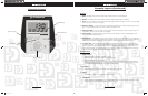
Fit the Cable Bead into the slot at the top of the Stationary Hook by pulling up on the Tension Cable 3.
to move the Sliding Hook toward the Stationary Hook. Once the Cable Bead is in place, release the
Tension Cable. The Cable Bead should remain in the Stationary Hook under tension.
Plug the wire from the Console Mast into the wire from the Console Mast Receiver.4.
Feed the slack in the wire and Tension Cable down into the Console Mast Receiver.5.
Slide the Console Mast into its housing on the frame. Be careful not to pinch the wire or tension cable 6.
while doing so, this could damage the wire.
Once the Console Mast is inserted into the frame, slide the Console Mast Cover up the Mast to allow 7.
access to the bolt holes at the bottom of the Mast. Attach the Console Mast to the Receiver using
three M8 bolts.
Once the bolts are tightened down, snap the tabs on the Console Mast Cove into place on the Side-8.
cases.
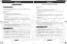
Step 3: Console Assembly
Hold the Console up to the top of the Console Mast and attach the three wires from the Mast to the 1.
back of the Console.
Fasten the console to the console mast using four M5 x 15mm bolts.2.
Note: Be careful not to pinch the wires while doing this, doing so could cause the unit to operate
incorrectly.
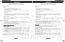
Step 4: Footpad Assembly
Place the left footpad on top of the fl at plate on the left arm of the unit, and line up the holes in the 1.
footpad with the holes in the arm.
Place 2 of the 5/16” x 2” bolts into the holes in the plastic footpad and through the holes in the steel 2.
plate and steel tube.
Place 1 of the 5/16” x ¾” bolts into the third hole in the plastic footpad and through the steel plate.3.
Thread three of the nylon-lined lock nuts onto the bottom of each bolt. Tighten each bolt with the M6 4.
hex wrench while holding the nut with the included open-ended wrench. Tighten until the footpad is
snug and tight on the metal plate.
Repeat the above step with the right footpad.5.
Peel the backing paper off the foam footpad inserts and stick them onto the plastic footpads. 6.
500Ef OM.r1.indd 6-7500Ef OM.r1.indd 6-7 6/11/2008 9:23:43 AM6/11/2008 9:23:43 AM