


4
8
6
4
2
1
3
5
7
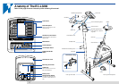
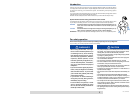
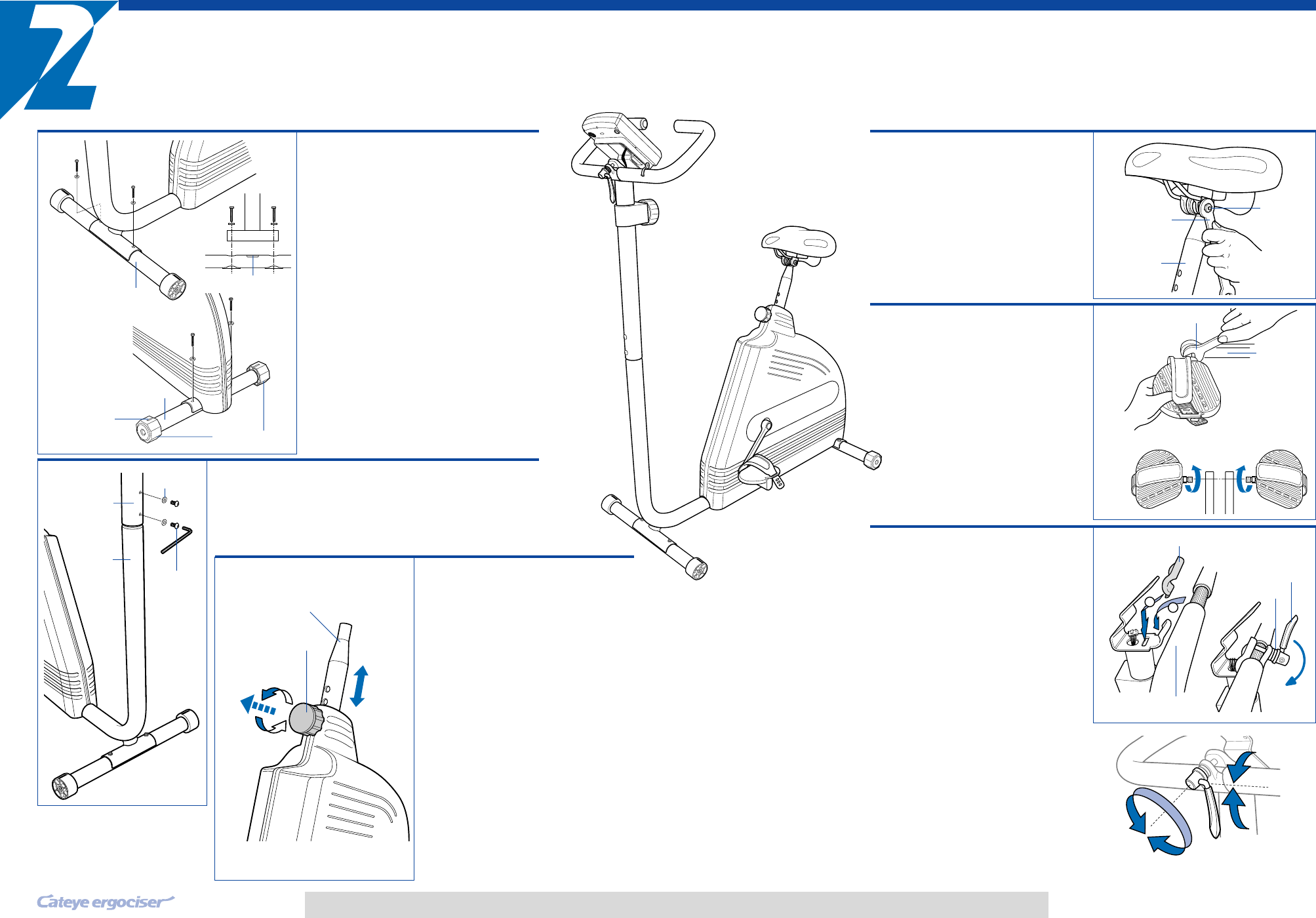
Assembly
Assemble the unit according to the following procedure. Learn how to
adjust each part as well.
* In addition to the tools provided, please prepare a screw driver.
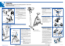
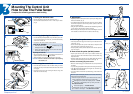
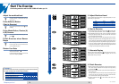
1. Attaching the leg pipes
• Remove the two screws from each leg pipe.
• Place the front leg pipe under the front end of
the main body as Fig. 1 and fasten it with the
screws securely.
• Place the rear leg pipe under the rear end of
the main body as Fig. 2 and fasten it equally.
CAUTION: Place the leg pipes with the "TOP"
mark facing upward.
ADJUSTMENT: Turn the level adjusters if nec-
essary, in order to compensate the
floor unevenness.
REFERENCE: When the marking line is at the
top, the rear leg is at the same level
as front.
2. Mounting the handle post
• Attach handlebar post to base post and secure with fastening
screws.
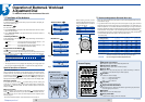
3. Seat post position
(ADJUSTMENT)
• Turn the seat post knob clockwise and coun-
terclockwise and pulling it allows the seat
post to slide up and down.(Fig.4)
• Adjust the seat post to an appropriate height
and release the seat post knob, and move
the seat post slightly up or down.
• The spring inside the seat post knob drives
the pin into the nearest hole on the seat post
and turn it clockwise until the seat post can-
not wobble.
• The pitch of the seat post hole is 1 inch
(approx.25mm).
CAUTION: Confirm that the pin of the seat
post knob must be in the hole
securely.
CAUTION: Do not pull the seat post knob
while mounted. The seat post
may drop down suddenly.
Fig. 2
Marking line
Pipe with casters
Fig. 1
TOP mark
1
2
3
Level adjusters
Rear
Front
Rear leg pipe
Pull
Loosen
Handlebar post
Fig. 3
Seat post
Pitch 1" (approx. 25 mm)
Seat post knob
Fig. 4
Handlebar
post
fastening
screw
Belleville
spring
Base post
5
EC-L32OO
1
2
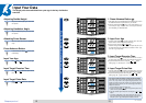
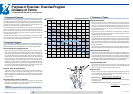
4. Mounting the saddle
• Lift up the seat post to a proper height for
saddle mounting.
• Mount the saddle at the top of the seat
post as Fig. 5.
• Adjust the saddle angle to make it horizon-
tal, and use the #13 end of the spanner
wrenches to tighten the nuts from both
sides.
5. Attaching the pedals
• Attach the pedals to the crank as Fig. 6
and fasten them firmly using the #15 end
of the wrench provided.
• Be sure to identify R and L of the pedal
with the engraved mark.
• Fasten clockwise the R pedal, and coun-
terclockwise the L pedal. (Fig. 7)
6.
Mounting the handlebar and
adjusting the handlebar grip
(ADJUSTMENT)
• Place the Handlebar clamp bracket and
the handle bar into place. (fig 8)
• Place both washers provided onto the Quick
release and screw it into the handlebar clamp
assembly until there is a loose fit. The Quick
release works like a clamp, test it to determine
when it is open (clamp assembly will be
loose). Test for proper tightness using the le-
ver action to close the Quick Release. If at
this time the handle bar is too loose open the
Quick Release lever and turn the screw por-
tion into the Handlebar clamp bracket 1 to 2
turns. Repeat the Test process until the
handle bar is held tightly into place when the
lever is closed and loose enough to adjust the
bar when the lever is open.
REFERENCE: Be sure that when you close
the Quick Release lever it
snaps firmly into place.
6
5
4
Assembly completed.
(Control Unit already mounted)
#13 Wrench
Seat post
Nut
Quick release lever
Tighten
Fig. 7
#15 Wrench
Crank
Fig. 8
Left(L) Front Right(R)
Fig. 6
Fig. 5
Tighten
(Lay down)
Loosen (Raise)
Handlebar clamp bracket
Washers
Handleber
Turn the quick relaese lever
for adjustment