Cateye Ergociser Series 1000 Service Manual
30
EC-1200 EC-1600 EC-3600 EC-3700
Applicable Models:
ES-6
ES-6
Fig. 1
Control Unit
Cable Connector
Fig. 2
Screw
Control Unit
Fig. 3
Substrate
Substrate
Fixing Screw
Connector
Fig. 4
Silicon
Fig. 5
Control Unit
Upper Body
Panel Keyboard
Fig. 6
Silicon
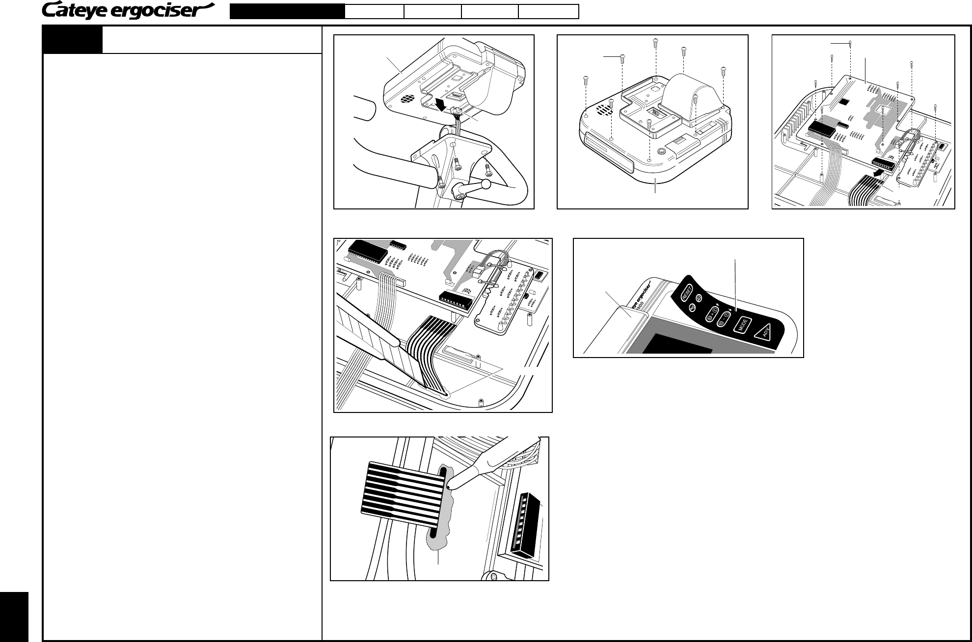
Replacing the Panel Keyboard
1. Remove the control unit by loosening four screws. Also
remove the cable connector from the control unit. (Fig. 1)
2. The control unit can be separated into upper and lower parts
when the eight screws on the bottom of the lower body of the
unit are removed (Fig. 2). Be careful to separate them slowly
since the upper and lower bodies are connected with a flat
cable.
3. Remove the connector on the panel keyboard which is located
at the upper body side, loosen the nine screws on the
substrate, and remove them from the upper body. (Fig. 3)
4. Since the panel keyboard is fixed to the control unit with
silicon, cut the silicon with a sharp cutter (Fig. 4). Peel the
panel keyboard off the surface of upper body. (Fig. 5)
5. If the silicon remains at the upper body, remove it thoroughly.
6. Place the brandnew panel keyboard. The cable from the
keyboard should be pulled in through the hole on the upper
body. Press and adhere the panel keyboard in position.
7. Apply silicon at two depicted areas to prevent intrusion of
sweat. (Figs. 4 and 6)
8. Mount the substrate and fix it with nine screws, and insert the
connector of the panel keyboard. (Fig. 3)
9. Put the upper and lower body together, and fix them with eight
screws.
10. Connect the cable connector to the control unit, and mount the
unit to the main unit.
Replacing the Panel Keyboard


