


18
Bowex
®
TreadClimber
®
Owner’s Manual
Assembly Guide
Step 8: INSTALLING THE CONSOLE/
HANDLEBAR ASSEMBLY
Locate the following for this step:
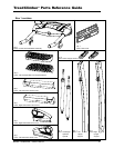
PARTS:
• TreadClimber
®
Base & Treadle Assembly from
Step 7.
• Console/Handlebar Assembly
HARDWARE:
• Six (6) 5/16” x 1” Button Head Screws
• Six (6) 5/16” Flat Washers SAE
TOOLS:
• 3/16” Hex Key (included)
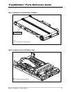
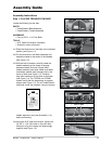
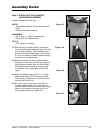
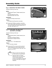
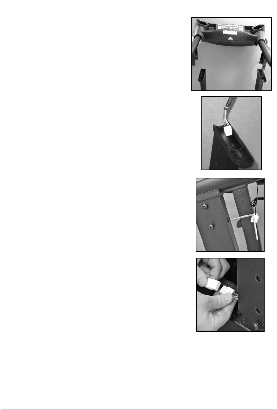
8-1 With the help of another person, carefully lift
the console/handlebar assembly above the tops
of the upright supports. Feed the cable down
the top of the right upright support (see Figure
8-1 & 8-1A). Make sure cable extends through
the bottom of the right upright.
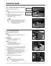
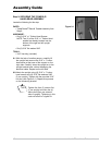
8-2 Slide the brackets on the console/handlebar
assembly into the tops of the upright supports—
both sides at the same time. Be careful when
sliding the console/handlebar assembly onto
the uprights to avoid damaging the electrical
cable.
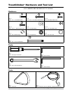
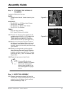
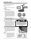
8-3 Attach the upright using (6) 5/16" x 1" button
head screws and (6) 5/16" flat washers SAE
(3 per upright). Tighten with the provided 3/16"
hex key (see Figure 8-2).
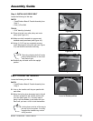
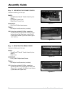
8-4 Pull out the wire connector at the bottom of
the right upright support. Firmly connect the
electrical cable at the bottom of the right upright
support to the cable on the right side of the
base upright bracket (see Figure 8-3).
Figure 8-2
Figure 8-1
Figure 8-1A
Figure 8-3