


20
Bowex
®
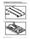
TreadClimber
®
Owner’s Manual
Step 10: ATTACHING THE HYDRAULIC
CYLINDERS
Locate the following for this step:
PARTS:
• TreadClimber
®
Base & Treadle Assembly from
Step 9.
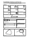
HARDWARE:
• Two (2) 5/16” x 1-1/2” Button Head Screws
• Two (2) 5/16” Acorn Nuts
• Two (2) 5/16” x 1” Button Head Screws
• Two (2) 5/16” Flat Washers
TOOLS:
• 3/16” Hex Key (included)
• 9/16” Open End Wrench (included)
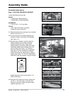
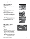
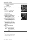
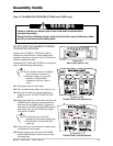
10-1 First bolt the dial end of the cylinders to the
uprights using (1) 5/16" x 1-1/2" button head
screw and (1) 5/16" acorn nut, per side.
Tighten with the provided 9/16" open end
wrench and 3/16" hex key (see Figure 10-1).
10-2 Make sure that the white arrows located on
the Workout Level Setting Dials at the top of
the Hydraulic Cylinders face the rear of the
machine where you can easily see them during
your workout.
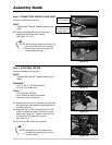
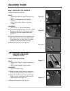
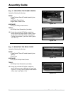
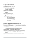
10-3 Starting on the right side, pull the cylinder
down and place the eyelet on the Cylinder
Stud protruding from the treadles. Attach the
hydraulic cylinder using (1) 5/16" x 1" button
head screws and (1) 5/16" flat washers (see
Figure 10-2).
10-4 Repeat this process on the left side.
NOTE: If having difficulty placing
hydraulic cylinder(s) on treadle
stud, loosen lower upright
screws, place cylinder on the
stud and retighten the upright
screws.
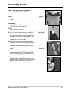
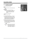
Step 11: INSPECTING ASSEMBLY
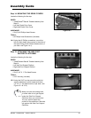
11-1 Remove the protective plastic film from the
console face. Inspect all attachments you have
made thus far and tighten all bolts securely
before proceeding to Step 12.
Figure 10-1
Figure 10-2
Assembly Guide