Altivar
®
58 TRX AC Drives
Wiring Recommendations
107
09/2003
© 2000–2003 Schneider Electric All Rights Reserved
Using a Line Contactor or an Output Contactor
When controlling the power with a line isolation contactor, avoid frequently
opening and closing the line contactor as this could cause premature failure
of the drive controller. Use inputs LI1 to LI4 to start and stop the drive
controller. Limit operations of the line contactor to less than once per minute.
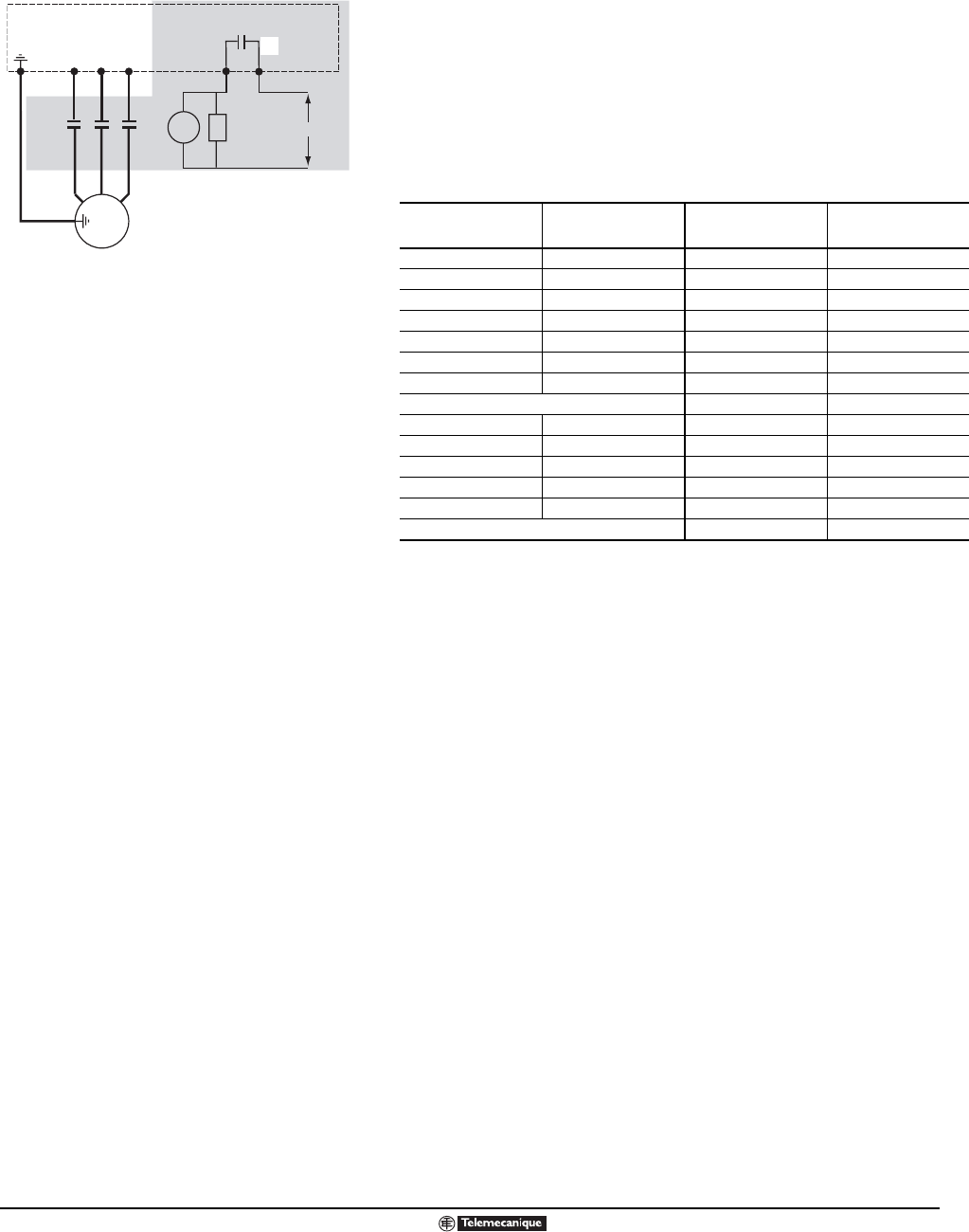
To use an output contactor, use the wiring diagram to the left for guidance
and set relay R2 to the Output Contactor Command function. In the wiring
diagram at left, the shaded portion is to be added to the output of either the
single-phase wiring diagram or the three-phase wiring diagram on page 108.
The recommended output contactors are shown in the table below.
KM2 KM2
ATV58H••••• LC1- ATV58H••••• LC1-
U09M2 D25
◆
U18N4 D25
◆
U18M2 D25
◆
U29N4 D25
◆
U29M2 D25
◆
U41N4 D25
◆
U41M2 D25
◆
U72N4 D25
◆
U72M2 D25
◆
U90N4 D25
◆
U90M2 D25
◆
D12N4 D25
◆
D12M2 D32
◆
D16N4 D25
◆
D23N4 D4011
◆
D16M2 D40
◆
D28N4 D40
◆
D23M2 D80
◆
D33N4 D50
◆
D28M2 D80
◆
D46N4 D80
◆
D33M2 D80
◆
D54N4 D8010
◆
D46M2 F115
◆
D64N4 F115
◆
D79N4 F115
◆
◆ Refer to the Digest for control voltage information.
U
V
W
U1
W1
V1
M
3 Phase
R2A
KM2
R2C
KM2 TS
120 VAC
TS = Transient suppressor
LineCont.eps
Wiring Diagram for Output Contactor
◆ See Specifications section for
contactor ratings.
◆


