(No.YA139)1-25
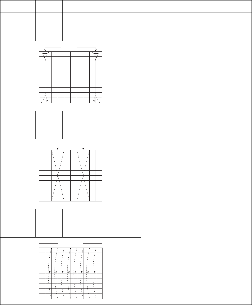
CORNER PIN
adjustment
Signal
generator
Remote
control unit
[4. DEF]
8. COR-UP
9. COR-LO
- PAL CORNER PIN -
(1) Receive a PAL crosshatch signal.
(2) Select 8. COR-UP.
(3) Set the initial setting value of 8. COR-UP.
(4) Select 9. COR-LO.
(5) Set the initial setting value of 9. COR-LO.
(6) Adjust 8. COR-UP and 9. COR-LO so that the
vertical lines at the four corners on the screen are
straight.
- NTSC CORNER PIN -
(1) Receive a NTSC crosshatch signal.
(2) Make similar adjustment of NTSC CORNER in the
same way as for "PAL CORNER".
H. PARALLEL
adjustment
Signal
generator
Remote
control unit
[4.DEF]
10. ANGLE
- PAL H. PARALLEL -
(1) Receive a PAL crosshatch signal.
(2) Select 10. ANGLE.
(3) Set the initial setting value of 10. ANGLE.
(4) Adjust 10. ANGLE to optimize the trapezium
distortion at the centre of the screen.
- NTSC H. PARALLEL -
(1) Receive a NTSC crosshatch signal.
(2) Make similar adjustment of NTSC H. PARALLEL in
the same way as for "PAL H. PARALLEL".
H. BOW
adjustment
Signal
generator
Remote
control unit
[4.DEF]
11. BOW
- PAL H. BOW -
(1) Receive a PAL crosshatch signal.
(2) Select 11. BOW.
(3) Set the initial setting value of 11. BOW.
(4) Adjust 11. BOW to optimize the horizontal arc
distortion.
- NTSC H. BOW -
(1) Receive a NTSC crosshatch signal.
(2) Make similar adjustment of NTSC H. BOW in the
same way as for "PAL H. BOW".
(3) Press the [DISPLAY] key twice to return to the
normal screen.
Item
Measuring
instrument
Test point Adjustment part Description
Straigt
Parallel
Straight


