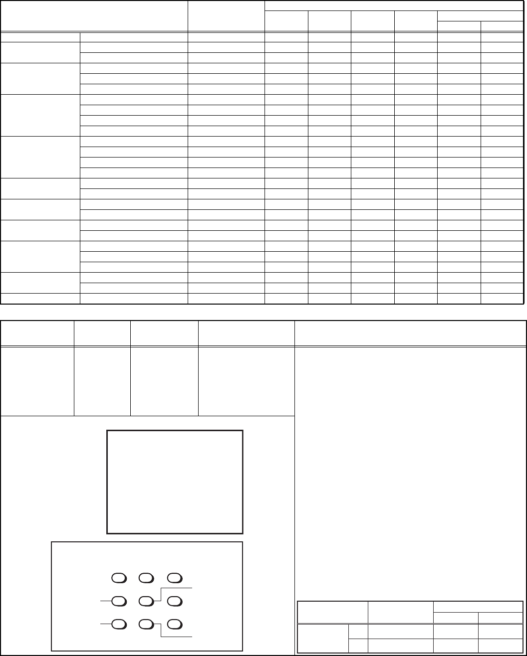
1-18 (No.YA139)
4.7.4 VIDEO CIRCUIT ADJUSTMENTS
• The setting (adjustment) using the remote control unit is made on the basis of the initial setting values.
• The setting values which adjust the screen to the optimum condition can be different from the initial setting values.
• Do not change the initial setting values of the setting (adjustment) items not listed in "ADJUSTMENT PROCEDURE".
• The initial setting values in parenthesis ( ) are fixed offset values, needing no further adjustment.
Adjustment item Variable range
Initial setting value
PAL SECAM
NTSC3.58 NTSC4.43
COMPONENT (V-2)
525i 625i
1. SCREEN BRI 0 ~ 63 32 32 32 32 32 32
2. CUTOFF B 0 ~ 63 (-32 ~ +31) 11 11 11 11 (-3) (-3)
G 0 ~ 63 (-32 ~ +31) 7 7 7 7 (-5) (-5)
3. WDR R 0 ~ 63 (-32 ~ +31) 32 32 32 32 (0) (0)
G 0 ~ 63 (-32 ~ +31) 32 32 32 32 (0) (0)
B 0 ~ 63 (-32 ~ +31) 45 45 45 45 (0) (0)
4. BRIGHT RF 0 ~ 63 (-32 ~ +31) 39 39 39 39 --- ---
VIDEO 1(COMPOSITE/S) (-32 ~ +31) (-1) (-1) (-1) (-1) --- ---
VIDEO 2(COMPONENT) (-32 ~ +31) (0) (0) (0) (0) (0) (0)
VIDEO 3(COMPOSITE) (-32 ~ +31) (0) (0) (0) (0) --- ---
5. CONT. RF 0 ~ 63 32 32 32 32 --- ---
VIDEO (-32 ~ +31) (+2) (+2) (+2) (+2) (+2) (+2)
RF 16:9 (-32 ~ +31) (0) (0) (0) (0) --- ---
VIDEO 16:9 (-32 ~ +31) --- --- --- --- --- ---
6. COLOUR RF 0 ~ 63 (-32 ~ +31) 42 32 37 (-3) --- ---
VIDEO (-32 ~ +31) (-1) (0) (-4) (0) (+4) (-5)
7. TINT RF 0 ~ 63 (-32 ~ +31) --- --- 27 (-4) --- ---
VIDEO (-32 ~ +31) --- --- (0) (+11) --- ---
8. SHARP RF 0 ~ 63 22 22 22 22 --- ---
VIDEO 0 ~ 63 35 35 35 35 15 15
9. Y DELAY RF 0 ~ 15 9 7 12 7 --- ---
VIDEO 0 ~ 15 7777------
S-VIDEO 0 ~ 15 9 10 11 11 --- ---
10. TINT DVD VIDEO, S-VIDEO 0 ~ 63 34 32 32 32 --- ---
COMPONENT (-32 ~ +31) --- --- --- --- (-2) (-2)
11. AMP T.SHARP RF, VIDEO 0 ~ 63 0 0 0 0 0 0
Item
Measuring
instrument
Test point Adjustment part Description
WHITE
BALANCE
(Low light)
adjustment
Signal
generator
Remote
control unit
[2. V/C]
2. CUTOFF (B)
2. CUTOFF (G)
SCREEN VR
[In HVT]
Note:
• Set PICTURE MODE (VSM) to "BRIGHT".
- COMPOSITE WHITE BALANCE -
(1) Receive a PAL black and white signal (colour off).
(2) Select 2. V/C from the SERVICE MENU.
(3) Select 2. CUTOFF (B) and (G).
(4) Set each value to initial setting value with the [4] /
[7] keys and [5] / [8] keys.
(5) Turn the SCREEN VR fully counterclockwise, then
slowly turn it clockwise to where a red, blue or
green colour is faintly visible.
(6) Use the [4] / [7] and [5] / [8] keys to adjust so that
the other 2 colours appear white.
(7) Turn the SCREEN VR to where the single
horizontal line glows faintly.
(8) Press the [DISPLAY] key twice to return to the
normal screen.
- COMPONENT WHITE BALANCE -
(1) Receive a PAL component black and white signal
(colour off).
(2) Select VIDEO-2 SET from the MENU and set
VIDEO-2 SET to COMPONENT.
(3) Adjust COMPONENT WHITE BALANCE in the
same way as ”COMPOSITE WHITE BALANCE”.
Adjustment Item
Variable
Initial setting value
range
2. CUT OFF
B 0 ~ 63(-32~+31)
0 ~ 63(-32~+31)
(-3)
G (-5)
11
7
COMPOSITE COMPONENT
PAL
2. CUTOFF
(B)
(G)
**
**
(
**
)
(
**
)
V/C
G CUTOFF (
)
12 3
4
789
56
B CUTOFF (
)
B CUTOFF (
)
G CUTOFF (
)
REMOTE CONTROL UNIT
